Bauer 707 AM Broadcast Transmitter
Following donation of the 1970s radio studio equipment to the Texas Broadcast Museum (see the blog), a search commenced for the next big project. Restoring a classic radio transmitter had been on the “planned project” list for some time, but no suitable (or practical) candidate could be found. Recently, however, a nearby station was looking to clear out space and get rid of gear that had been sitting around unused for years (or more likely decades). Among the items in the transmitter building was a Bauer 707 AM broadcast transmitter.
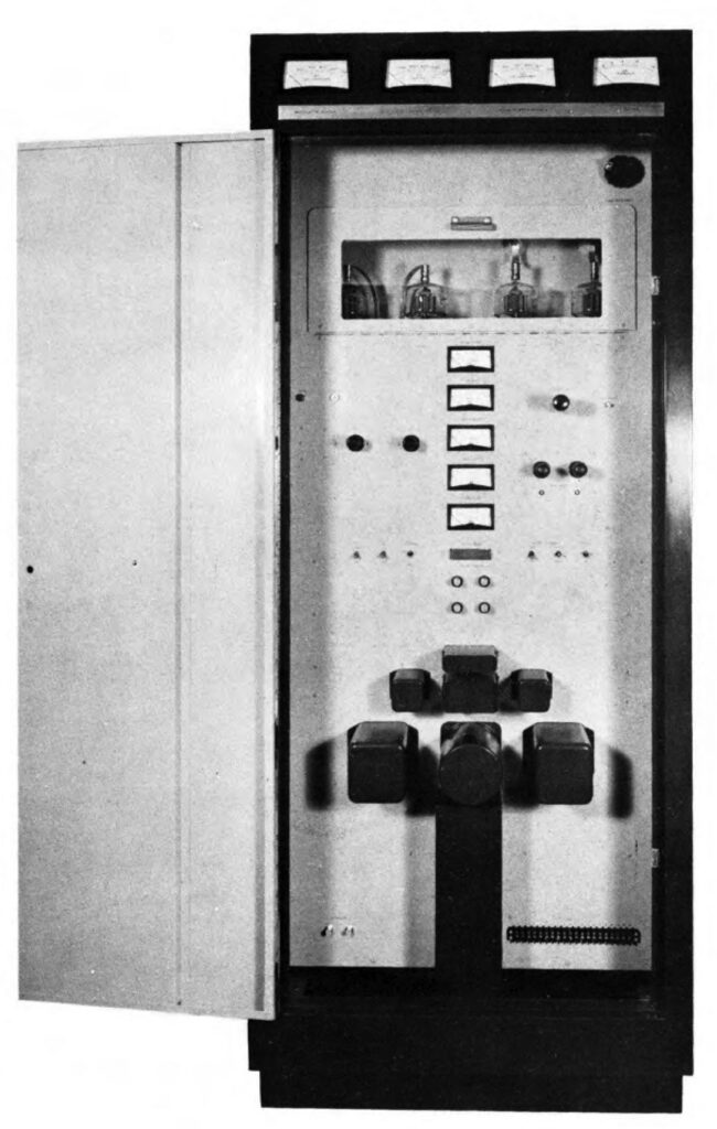
Bauer 707 Transmitter from the Sparta/Bauer catalog circa 1970. (Source: Sparta/Bauer.)
The Bauer 707 employs high-level modulation and can operate on any carrier frequency in the range from 540 kHz to 1600 kHz. With modifications, operation can be extended to 30 MHz. The transmitter is normally supplied pre-tuned to the desired channel. Bilevel power operation is standard with this transmitter; it can be switched between any two of the following three power levels: 250 W, 500 W, 1000 W.
About the 707
The Bauer 707 is an interesting design in that it is all-tube, using a pair of 4-400s for the modulator and another pair of 4-400 for the final amplifier. The ability to extend the operating frequency well into ham radio bands has given this model extended life in ham radio circles. Several operators have documented the necessary modifications.
Modifying a Bauer 707 for ham operation involves moving its operating frequency from the Medium Wave band (540–1600 kHz) to amateur bands such as 160 meters and/or 75/80 meters. The conversion requires retuning the RF tank circuits, updating the VFO, and narrowing the high-level plate modulation audio bandwidth.
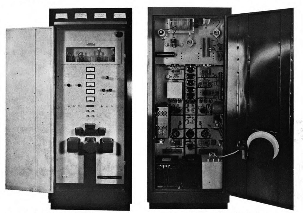
Bauer 707 transmitter internal view. (Source: Sparta/Bauer.)
The Bauer 707 was originally designed as a kit for broadcast engineers, which makes its layout and documentation relatively accessible for study. Converting such a vacuum-tube transmitter for amateur radio service is a significant technical undertaking, which is a good reason to do it!
General areas of modification typically include:
- Frequency Adjustment: Adapting the transmitter for the 160-meter or 75/80-meter amateur bands requires modifying the tuned circuits in the RF stages. This involves calculating new values for inductance and capacitance of specific components to allow the transmitter to resonate at higher frequencies than the standard AM broadcast band.
- Excitation: Vintage broadcast transmitters typically rely on a fixed crystal for operation on the assigned frequency. Modern conversions, however, often utilize Direct Digital Synthesis (DDS) to provide the frequency agility needed for amateur radio use.
- Audio Processing: Amateur radio regulations and standard practices require narrower audio bandwidth than commercial broadcasting. Modifications are usually made to the speech amplifier and modulation stages to restrict the frequency response to a range suitable for voice communication, typically between 300 Hz and 3,000 Hz.
The Bauer 707 transmitter was introduced in 1960 by Bauer Electronics (San Carlos, CA). The company was later acquired by Sparta Electronics (Sacramento, CA) and sold under the name “Sparta Bauer.” An updated version of the model 707 was introduced in 1970 that included several small changes to the original unit, including increased wattage of some power resistors.
Documentation
In preparation for this project, a manual was created that brings together all of the available documentation on the Bauer 707, including the following:
- Bauer AM Broadcast Transmitter Model 707 Instruction Book, Bauer Electronics, San Carlos, CA, September 1961.
- Bauer Model 707 Product Brochure, Bauer Electronics, San Carlos, CA (undated).
- “Design Features of a Broadcast Transmitter Kit,” Paul Gregg, Broadcast Engineering, Overland Park, KS, June 1960.
- Bauer Model 707 Assembly Instructions, Bauer Electronics, San Carlos, CA (undated).
- Sparta/Bauer AM Broadcast Transmitter Model 707 Instruction Book, Sparta Electronics, Sacramento, CA, July 1970.
The text above was developed in part from these documents.
The expanded Bauer 707 User and Maintenance manual is available for download on the Available Downloads page. A printed version is available for purchase on the Available Printed Documents page.
The Project Begins
After arranging for shipment from the radio station in Northern California, the Bauer 707 arrived and an assessment was made of the work ahead. The front views are shown below. The tubes were removed prior to shipment. They will be replaced at the end of clean-up work.


Internally, the rig is quite dirty, which is to be expected since this transmitter is more than 50 years old, and by the look of it, has not been operative for some time.

There are some missing parts in the final RF assembly, notably the internal 1 kW dummy load (and perhaps other components).

The four power tubes (4-400) were not provided with the transmitter, but they are available elsewhere. As with the smaller tubes, the 4-400s will be installed last.

Looking at the photo above, the metal piece in the center of the PA compartment is an air pressure switch, designed to protect the tubes from damage if the cooling blower fails. The switch is rather primitive. A better solution will hopefully be found.
Day 1 — Disassembly (Heavy Metal)
A close inspection of the transmitter shows that with the exception of the high voltage (HV) components, the internal parts are relatively clean and appear to be in good condition. The high voltage components, however, are quite another story. High voltages, of course, tend to collect (attract) dust. What’s on the HV components and nearly all of the HV wiring is more that just dust; it’s more of a dirty film. The combination of normal dust accumulation over a period of many years (or even decades) combined with high humidity may have led to this problem. In any event, a significant cleanup effort is needed.
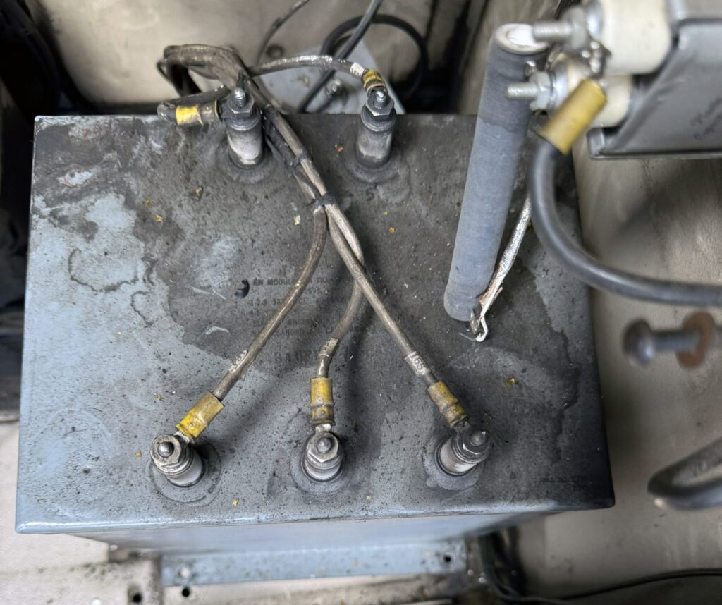
The photo below shows the modulation transformer. Note that the dirty film covers a significant portion of the insulators. This is a ready-made arc-over condition.
In addition to the HV devices, the floor of the transmitter is covered in the same greasy film, as shown below.
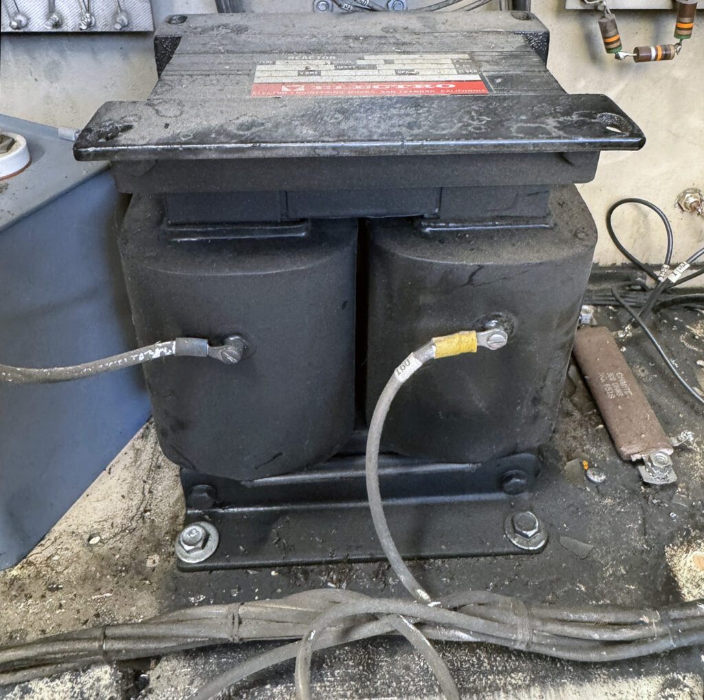
To facilitate cleanup (and eventual refinishing of the cabinet), all of the floor-mounted components were removed. This includes the modulation transformer, plate transformer, and reactors. The Sola voltage-control unit, which mounts on one of the side walls, was also removed. All of the components were cleaned and inspected. The end-result is shown below.
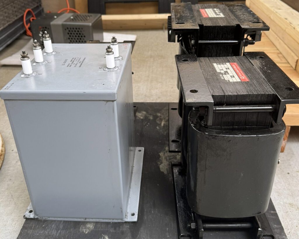
Component cleanup was done with a product called “Tub O’ Towels Heavy-Duty Multi-Surface Cleaning Wipes,” available on Amazon.com and perhaps elsewhere. They made cleanup surprisingly easy. One note, however, this product leaves a film that needs to be washed off with water or wiped off with a damp cloth.
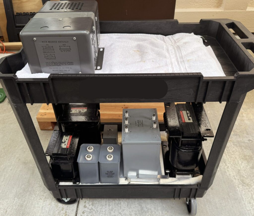
After cleanup. the HV components were placed on a storage cart for safe-keeping. They will be reinstalled as one of the last steps in the restoration project. With removal of these “heavy metal” components, the transmitter is also much lighter and easier to move around.
The photo below shows the floor of the transmitter with the HV components removed. A couple of things are evident: 1) the floor is a greasy mess, and 2) the HV wiring harness is a greasy mess.
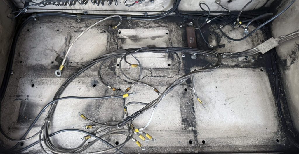
The condition of the wiring harness is a bit of a surprise. While the major HV components were cleaned up without too much effort, the wiring harness was not. The same cleaner (Tub O’ Towels) was used, but the film was very difficult to remove. I am hesitant to use a stronger solvent, such as acetone, for fear it might degrade the insulation. Since the HV wiring harness is relatively simple, I will probably just make up a new harness and get rid of the old one.
To efficiently clean the bottom mounting plate (shown above), it was necessary to remove the plate from the transmitter. Despite considerable efforts, the bottom plate could not be returned to like-new condition. The plate will therefore be sandblasted and refinished by the local powder coat shop.
Day 2 — Disassembly (High Voltage)
With the amount of dust and dirt covering the high voltage standoffs, removal of the two HV panels was required to adequately clean the assemblies. The photo below shows one of the two HV panels prior to removal.
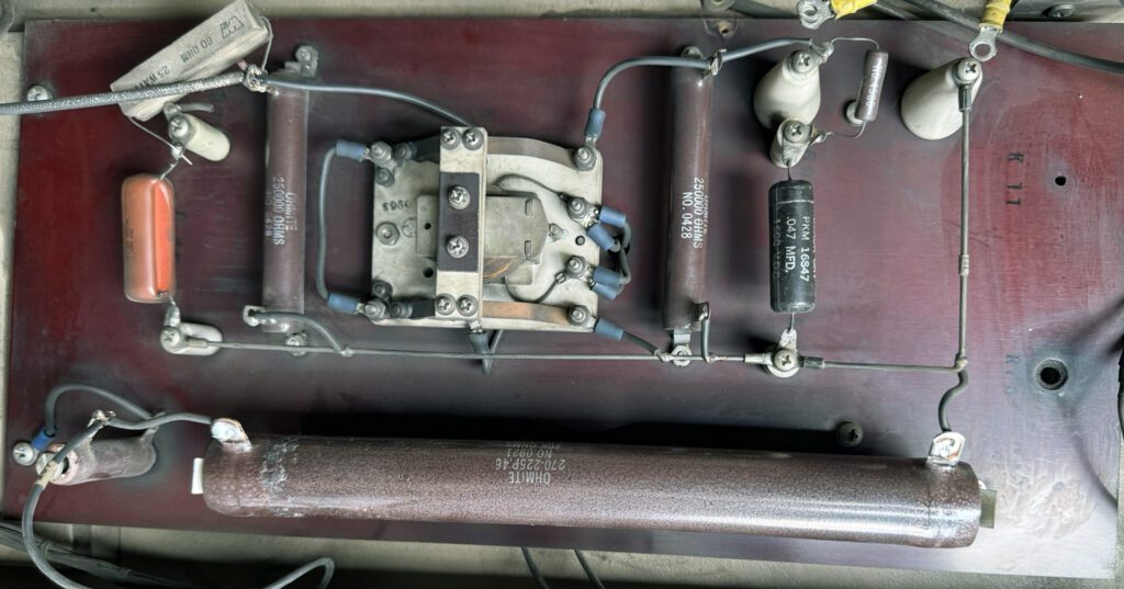
As noted previously, the HV wire harness needs to be replaced, so removal of the two HV panels facilitated that work.
While removing the panels, a really poor bit of maintenance was discovered, as shown below.
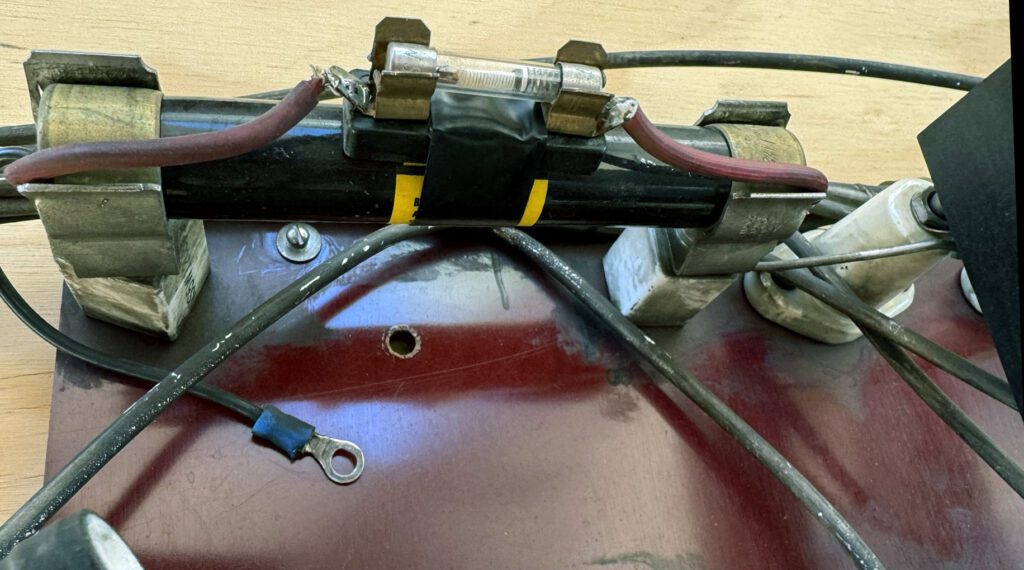
The long black component is a high voltage fuse, 1.5 A, 5 kV. That fuse is in the ground return path for the high voltage power supply. As such, it is a key link in the HV protection system. Note the 3AG fuse strapped to the HV fuse. That fuse is rated at 1.5 A, 125 V. At some point, the 5 kV fuse failed and was replaced with the 125 V fuse, providing essentially zero protection to the power supply. Bad. Really bad. Fortunately, an exact-replacement device is available (Buss HVJ 1-1/2) and has been ordered.
More to come…