About the Workbench
There’s no secret to setting up a workbench. Having said that, a few pointers may be helpful when creating a new work space or modifying an existing one.
I have been a fan of Heathkit test equipment since the Beatles were making records. And my workbench proves it.
The restoration work documented on this web site has served as an excellent excuse—err, reason—to build up a test bench. After I got serious about this long-term hobby, it became clear that I would need to acquire some test equipment. Over the years I accumulated, and later got rid of, a lot of audio test gear. Much of it was Heathkit products that I built from a kit. Readers who were interested in kit-building will recall there were two prices listed in the catalogue—the kit price and the assembled price. The kit price was always less, although often not by much. The real attraction of buying the kit was to build it.
Anyway, as I began my search for test equipment I focused initially on computer-based signal generators and analysis tools. Today, of course, a high-quality audio generator can be had for the cost of a good sound board and some software. The signal analysis side requires more hardware and more software. The PC-based measurement tools are easy to find and relatively inexpensive. They are also about as much fun to use as Microsoft Excel. Good tools, for sure, but not quite what I was looking for.
In what to me was an amazing discovery some years ago, there’s all kinds of stuff on eBay. I was late coming to the online auction thing, reasoning that I had enough stuff of my own; I really didn’t need to buy other people’s stuff. And then I did a search on the keyword “heathkit”. Eureka!
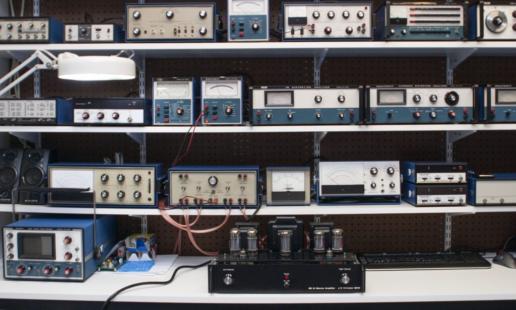
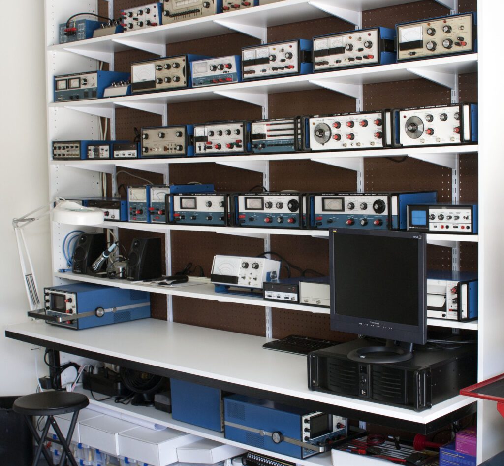
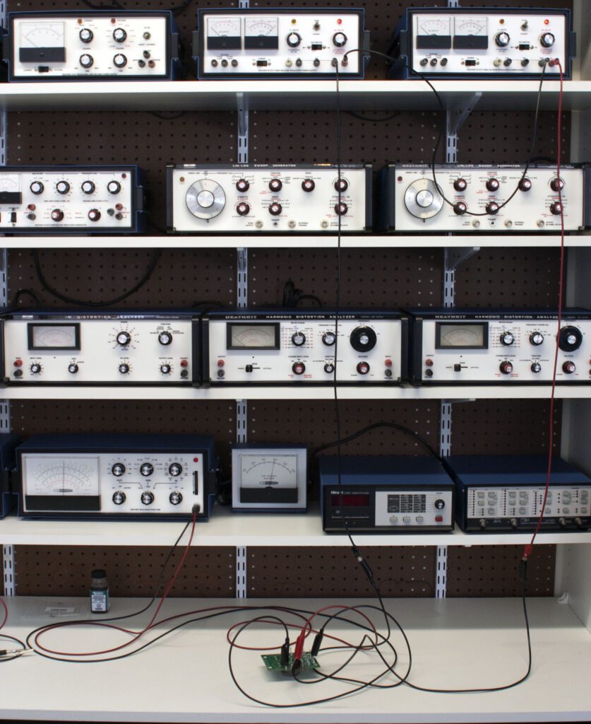
So began a years-long effort to acquire all manner of test equipment that would be helpful (dare I say essential) to my planned work. The photo above represents the first incarnation of the Heathkit-centric workbench. All of the instruments were produced in the 1970s, which I submit was the period where Heahtkit made its best test and measurement devices.
I really don’t like spending money; I like to look for bargains. The first piece of equipment I purchased from a nice guy on eBay included the following cautionary statement in the ad: “I turned the power on and the needle swung over to the right and I smelled something burning.” I bought it anyway, figuring this is a 35-year-old piece of hardware and at least one of the electrolytics probably had failed. I was right.
The desire to collect things aside, I would argue that building vacuum tube amplifiers (or other vintage devices) is best done with the tools of the era. That’s my story, anyway, and I’m sticking to it!
The fact of the matter is that the Heathkit test equipment I have collected and rebuilt actually does a very good job. If I had the need to measure distortion down to 0.01 percent or noise down to –120 dB I would need something other than what I have. But, for vacuum tube and classic audio gear, it fills the bill just fine.
A Known Load
A reference load is important when measuring the performance of an audio amplifier. Most common resistors of high wattage are wire-wound devices that may have appreciable impedance, which can adversely impact measurements at high audio frequencies. The stability of the load when hot is also important, since values may change with temperature (sometimes significantly). A load that varies with the applied signal power can result in incorrect determination of output power or in driving the amplifier harder than necessary for a particular test.
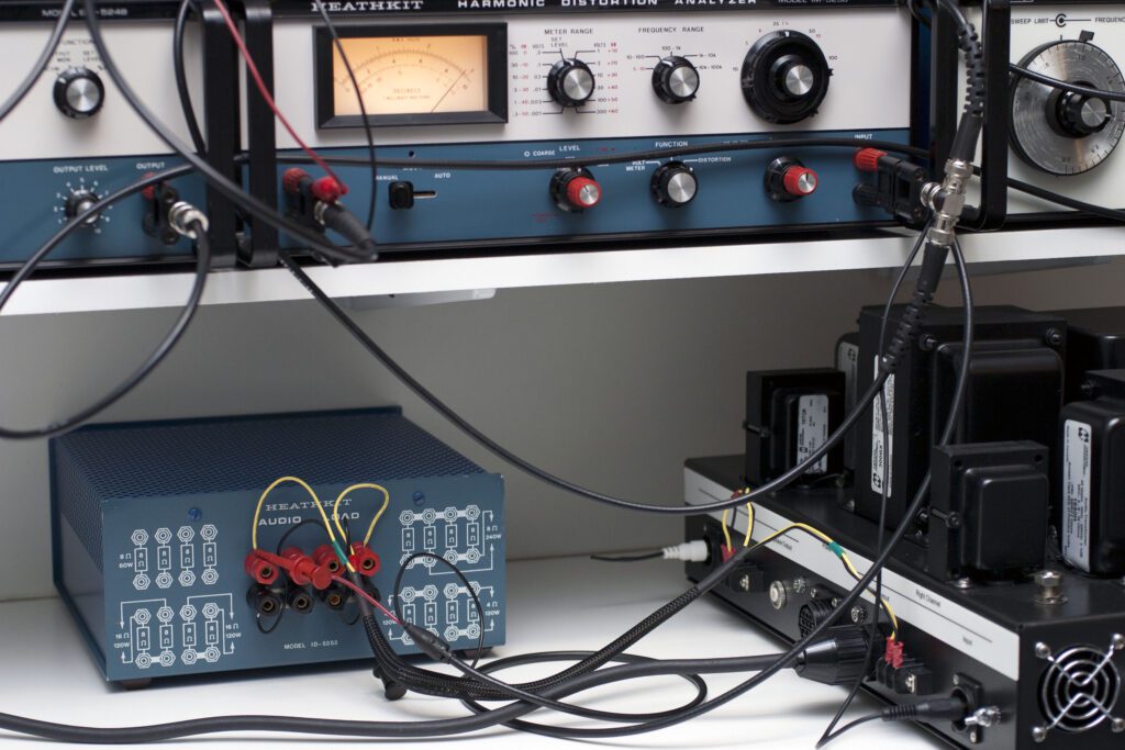
Ideally, a load is available on the bench that will connect to both channels of the amplifier under test. The loads should be identical so that measurements can be made on one channel and compared directly with measurements on the other channel.
Keep the leads from the amplifier to the load short and direct to minimize the effects of inductance and capacitance in the interconnecting wiring. Also ensure that wiring of sufficient size is used to connect the amplifier output with the load in order to minimize resistive loss.
A load that is capable of operating at various resistances (such as 4, 8, or 16 ohms) via strapping of terminals is useful as well.
Shown above is Heathkit audio load test set.
Voltmeter Calibration
Proper calibration of all test equipment is important. For an audio amplifier, power output is a key measurement parameter. That being the case, it is important that the ac voltmeters used on the bench are accurate and provide repeatable readings. Most audio test gear includes some form of audio voltmeter, which is typically specified to be accurate over a frequency range of at least 10 Hz to well above 100 kHz. Because power output is usually determined by measuring the ac voltage across a known (e.g., 8 ohm) load, an incorrectly calibrated voltmeter can adversely impact a number of parameters. Likewise, it is important that all voltmeters on the bench are matched within some small tolerance. A given signal fed to two different instruments should display the same voltage.
The steps for calibrating various instruments can be found in the documentation for those instruments. Typically, a signal of known value is fed to the instrument and the “meter calibrate” (or similar) trimmer potentiometer is adjusted so that the meter reads (or displays) the proper voltage. Because instruments can drift (age) over time, occasional calibration checks are recommended.
DC voltmeters should likewise be checked for proper calibration from time to time. While the tolerance of B+ voltages in typical audio amplifier circuits vary within +/–5 percent or so, troubleshooting can be simplified by having measurements that you can depend on. It is frustrating to measure the same voltage with two different instruments and get two different readings
Test Leads and Fixtures
Most hobbyists would agree that it is more fun to experiment with a circuit than to outfit the shop with the necessary test leads and fixtures. Nonetheless, proper test leads are essential to design and maintenance of electronics equipment. Leads that are too short to reach the equipment under test without moving the instrument from its typical location on the bench can be a source of frustration. Leads that are not rated for the voltages being used can be dangerous. Similar cautions apply to jumper leads used to temporarily connect one circuit point to another. Fortunately, a wide selection of pre-made quality test leads are available from a variety of manufacturers. Test lead cable may also be purchased for special applications, such as extra-long leads.
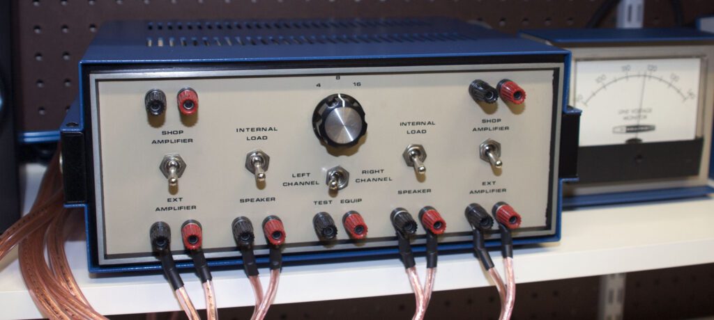
Test fixtures are a specialized form of test equipment designed to make measurements more efficient and/or accurate. A chance visit to eBay one day resulted in the audio load test fixture shown above. This is a Heathkit instrument, although it appears to be a custom unit intended for factory (or service center) quality control. I don’t think it was ever offered as a product to the public. Anyway, it illustrates the purpose of a test fixture, namely to make bench work more efficient.
Input terminals (right and left channels) are provided for a reference amplifier and the amplifier under test. The selected amplifier can then be switched to speakers or to internal loads of 4/8/16 ohms. A separate left/right output switch connects the selected channel to external test instruments. It is a very useful device.
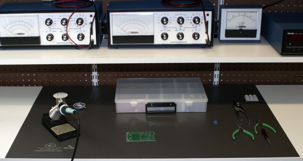
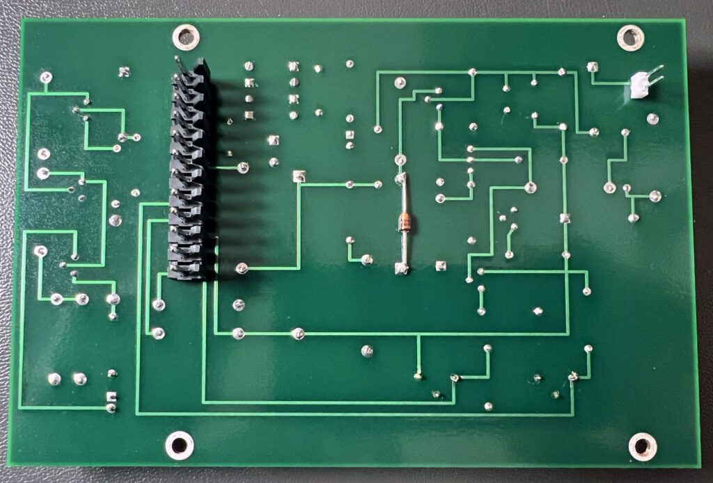
While is it possible to troubleshoot a circuit board within a larger assembly, it is not always easy to do so. Troubleshooting a PCB on the bench provides ready access to all components on the board. It also eliminates the possibility of collateral damage to other elements on the system while attempting to troubleshoot and repair a particular problem.
It is useful, therefore, to build up a test station for specific devices. One example is shown below.
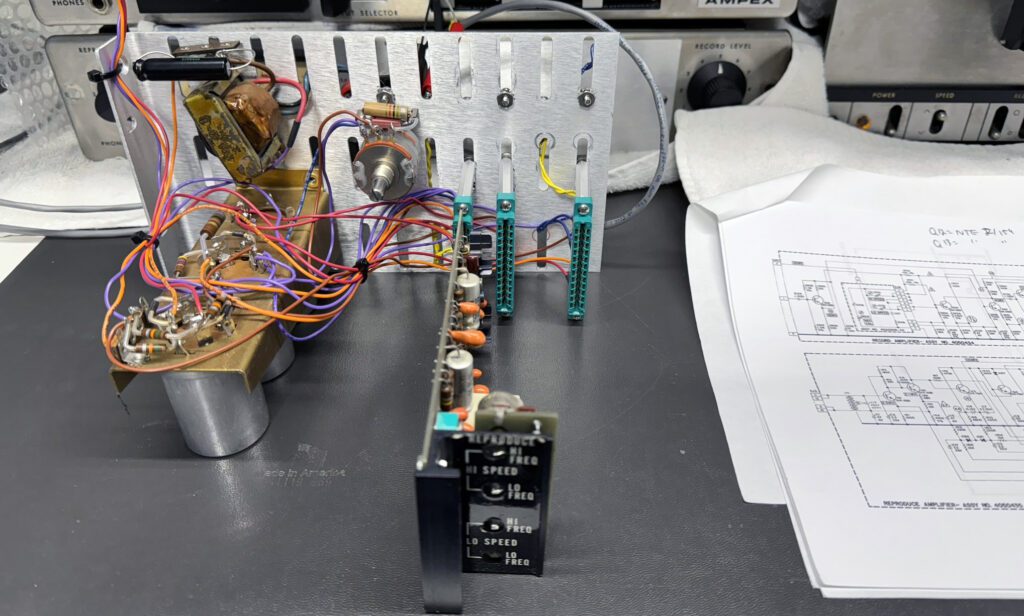
This test setup is used to check the three circuit boards in an Ampex AG-440 reel-to-reel tape deck. (See the Ampex AG-440 Tape Machine Restoration blog.) This simple arrangement, while not particular fancy, serves the purpose of providing a test station for the PCBs. This approach is reasonable for situations where only a few boards need to be checked. For higher volume applications, a more formalized setup is advisable.
Workbench Safety
Safety considerations must always be top-of-mind. In most projects, the point at which something might go wrong is probably the first power-up test. Even if all the proper pre-checks have been completed, things can still go wrong when power is applied for the first time.
Two common methods are used to reduce the possibility of problems at the first power-on stage. One requires a test instrument and the other a light bulb. Both are effective.
A variable ac source, capable of providing from 0 V ac to the rated line voltage (e.g., 120 V ac) to the load, can be used to slowly bring the ac power up while monitoring the current pulled by the unit. Be certain to observe all recommended safety precautions when using this type of instrument. As the primary voltage is increased, the line current is monitored. If excessive current is observed, the test is stopped and the problem is investigated.
The light bulb approach is simple and effective. With parts available from any hardware store, construct a circuit (using a proper enclosure) that puts a light bulb socket in series with the load under test. Have on hand incandescent bulbs of various ratings (e.g., 25 W, 60 W, 100 W). When power is first applied to the device under test, the bulb should glow dimly. If it glows brightly, there is very likely a short-circuit condition within the device. The light bulb test, thus serves two purposes: first it limits the inrush current into the device under test to a level below which damage can occur (in most cases), and second it provides an indication of problems in the device. Once the device under test has passed the light bulb test, it will need to be connected directly to the line power source for performance measurements.
Also be certain that bench power is on a circuit protected by a ground fault current interrupter (GFCI). The importance of safety around high-voltages cannot be over stated.
Chassis Work
It can be difficult to get a chassis done right and looking like it was produced by a professional. There are several approaches to achieve that goal. The easiest is to find a local vendor who will take your drawings and output a finished piece. These services may or may not be available locally, or be affordable
There are at least two alternatives for the hobbyist—do it yourself with your tools or do it yourself with someone else’s tools.
For those who do not have the tools, or just need help drilling and punching the chassis, there is an interesting option in some cities in the U.S. where work space and tools are made available to members at some specified monthly or hourly rate. A web search should turn up possible options.
For those who want to prepare the chassis using their own tools, one approach is to develop a full-size drill pattern drawing, which can be affixed to the chassis as a legend for drilling and punching.
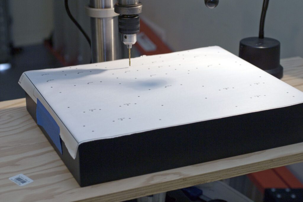
The drawing can be taped to the work surface or temporarily attached using a spray-mount product available in art stores (and elsewhere). The use of a drill pattern printout is shown above.
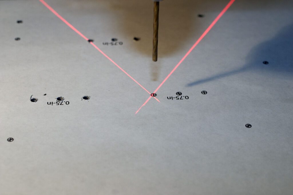
With the help of a good drill press, an accurate chassis can be prepared. Note that in the photo above, the location of drill holes is shown, and the size of those holes. The larger holes (e.g., 0.75-in) are made using a chassis punch.
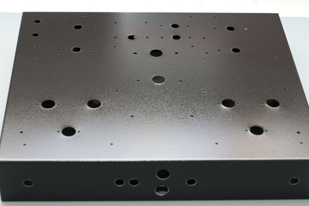
The chassis shown above took about 2 hours to prepare, from start to finish.
While it may be tempting to simply sketch a chassis layout, the results can sometimes be less than optimal. A better approach is to use a drawing program to create a final layout and then print the drawing for drilling, as suggested above. Programs such as Adobe Illustrator allow the user to create any number of layers, which can be individually manipulated. It is often useful to create layouts for the major components and then place them in the chassis drawing, moving each component around as needed to achieve the desired design. See the example drawing. This top view of a chassis layout shows all elements of the design, including circuit boards, transformers, and other components. In addition, the drawing provides a drill pattern for holes that need to be cut in the chassis, and the dimensions of the decorative Plexiglas trim piece. Each element (layer) can be hidden so that only the desired information is shown. For example, when all layers except the drill pattern are hidden, a drawing similar to the photo above is produced. While such a master drawing does take some amount of time to generate, it often saves time later in the project by providing an accurate representation of all elements of the design.
Looking at the example drawing you will note that some of the component legends are reversed. This is because the original drawing was done of the underside of the chassis. When viewed from the top, those legends are reversed.
The Work Space
Some hobbyists and experimenters have the luxury of a dedicated work space in which to build, modify, and test projects of various types. Others are not so fortunate; the work space is more of a timeshare proposition. In a shared work space, different interests compete for space, including (but not limited to) automobiles, bicycles, and household items. In a recent search for additional workbench space, I came upon a simple but effective solution that met the needs of my current and planned projects while still keeping peace in the family.
The approach was to use stock shelving items available at retail stores (Home Depot, Lowes, etc.) to build a large shelf structure that included a workbench with storage space below. The finished unit is shown above.
In planning the project I wanted to enclose the shelves so as to cover the test equipment and supplies on the shelving. Covers were desired because: 1) it looks nice, 2) it keeps dust off of the equipment, and 3) it affords some measure of security. Accomplishing the design objective for the doors was difficult in that I wanted a clear, unobstructed space when using the bench.
A simple solution was found to the cover requirement while wandering around Home Depot one day. Rather than use actual doors, why not use hanging panels to cover the shelving. Once removed, I would have clear access to all of the equipment on all of the shelves.
It appears from the photo below that all of the shelfs are enclosed with doors. Not so; it is actually five lightweight removable panels.
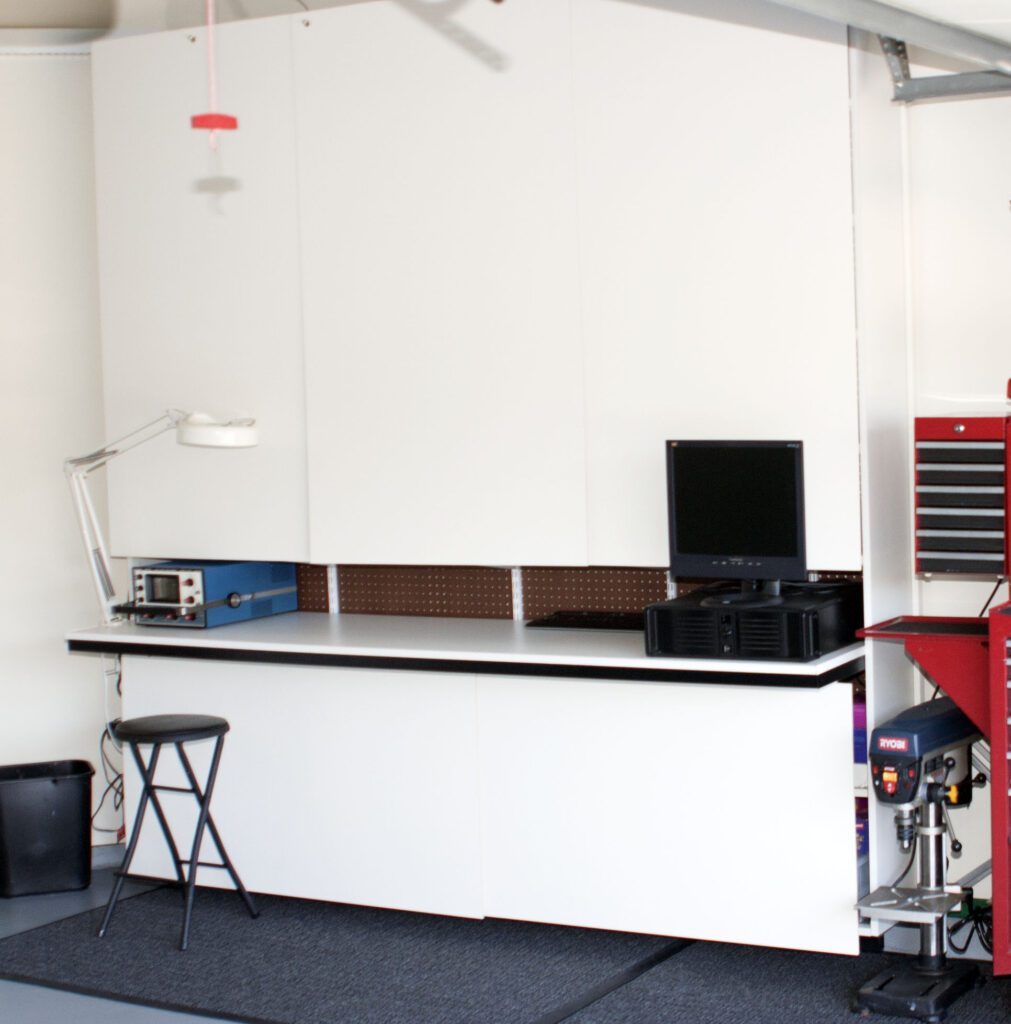
With this arrangement, I have easy access to all test equipment without stacking one upon another. Long power strips (6-ft in length) are placed along the back side of each shelf and the test equipment plugs into a nearby strip. The six power strips connect to a master power strip. A single switch removes power from all equipment.
The cost for the total project (including repainting the garage) was well below $750.
Another objective of the project was to build a shelving unit that could be repurposed if (when) the home is sold. The unit is flexible and looks nice.
No doubt your own workspace requires a specific solution. When it comes to storage, one size usually does not fit all. Still, I hope this gives you some ideas the next time you feel the need to reorganize your workbench.
Computer-Based Test Equipment
When building the workshop, I investigated but did not pursue the use of computer-based test equipment in my initial refurbishment work. After assembling a workbench of Heathkit test equipment, however, I decided to take another look at PC-based measurement. There are a number of software and hardware vendors in this space. For basic audio testing, I settled on the Audio Precision System One, itself a classic piece of audio test gear.
Computer-based instruments are available from a number of sources—from new units to previously owned units on eBay.
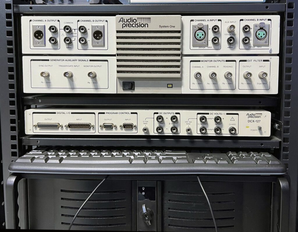
The cost of purchasing an instrument like the System One is certainly higher than individual Heathkit audio instruments. However, the increase in capabilities is considerable. I have found use for both classes of devices on my work bench.
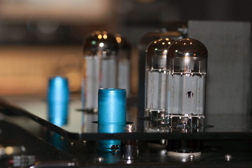
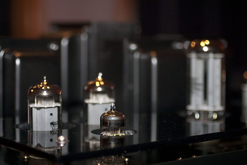
Vacuum Tubes
My projects over the years basically divide into two categories: classic radio station hardware, and vacuum tube amplifiers.
Within the selection offered by a given tube vendor, there are often a number of options with regard to price and services, particularly for applications considered to be for “audiophile” use. Services may include one or more of the following:
- Matching tubes—selecting tubes that have the same operating characteristics. This is valuable for push-pull power output stages, which require a good match between components for lowest distortion.
- Burn-in test, which tends to weed out tubes with inherent defects. This may be useful; however, as a buyer you might expect that this would be done before shipment anyway (maybe not).
- Low noise selection. Within any group of tubes of the same type, some may (for a variety of reasons) provide lower initial noise when operated in a typical circuit. This can be important for mic and phono preamps, where noise performance is critical.
- Low microphonics selection. As with noise, some tubes are more sensitive to vibration, which can be heard in the output of the device if the tube is used in low level circuits, such as mic and phono preamps.
For most projects, it makes sense to use some or all of these services, since: 1) it will usually result in you receiving a better device, and 2) the cost of the tube is usually a small percentage of the overall cost of the unit in which it is used. Having said all that, I wouldn’t spend twice as much for a tube that some guy says “sounds better” than another. That is an entirely subjective (and generally non-repeatable) “measurement.” It doesn’t matter what somebody thinks sounds good; it does matter what you think sounds good. If you have had good results with a particular type, then stay with your preference. Input from others is always helpful, but need not be a determining factor in your selection.
Special Purpose Chemicals
The need often arises in the shop for some special-purpose chemicals for equipment servicing, or for new construction.
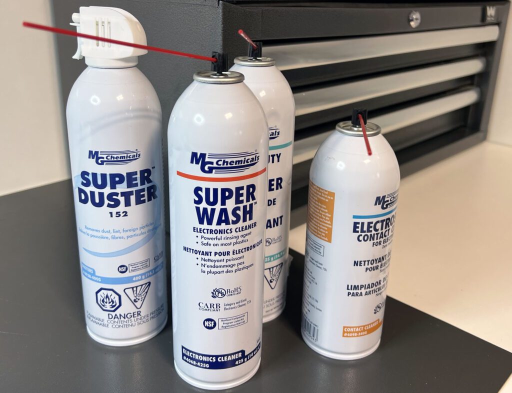
There exists a wide selection of chemicals from multiple vendors and supply houses. Some of the more common product categories include the following:
- Aerosol dusters
- Cleaning products
- Protective coatings
Within these broad categories, a number of product selections exist. Perhaps the most popular (or at least the ones I use regularly in my shop) include:
Flux remover. Because much of the work I have done recently involves refurbishing classic equipment, dealing with circuit boards loaded with far more solder flux than needed has become commonplace. There are some very good products on the market; I use the MG Chemicals Heavy Duty Flux Remover. These products do a good job of cleaning circuit boards of excess flux, which makes repair easier and results in a more professional finished look. More than one strength may be offered by the supplier. The stronger products may be harmful to some plastics and may be flammable. So, try the product on a test board first. Also, use adequate ventilation. Read and follow the manufacturer’s instructions.
Contact cleaner. This is a classic product category, used by technicians for decades. Back in the vacuum tube era, contact cleaner was essential for returning many radios and television sets to service. Improved products are available now, featuring various performance trade-offs. My preferred product is the MG Chemicals Electrosolve Contact Cleaner. This product does an excellent job—it is fast drying, safe on plastics, and leaves no detectable residue. Products of this class may be flammable, some extremely flammable. As before, read the manufacturer’s instructions carefully before use.
Dusters. These products are inexpensive and can be found at any office supply store. Some are better than others, but all are intended to blow dirt out of a confined space. Be sure when using these products to blow the dust out of the chassis, not just move it around. A related product category is the cold spray, which can be used to locate an intermittent circuit caused by temperature changes. The idea is that the PCB crack or cold solder joint can be made to fail if exposed to cold.
Electronics Cleaners. This class of products can be very useful when restoring old gear. These products are well-suited for cleaning many types of electronics hardware, including circuit boards. It is not a replacement for flux remover, but does a very good job of cleaning the “other side” of the board. I use the MG Chemicals Superwash Electronics Cleaner in the shop. This product is safe on plastics, leaves no residue, and evaporates quickly. Note that products of this class may be flammable. Never use them on live circuits or components that are hot.
Conformal Coatings. This is an interesting class of products that is used primarily for protecting circuit boards from fungus, moisture, corrosion, and chemical environments. A wide variety of coatings are available, each intended for a particular application. I use the MG Chemicals Acrylic Conformal Coating. This particular product sprays on and facilitates easy repair and rework. This class of product also helps prevent high-voltage arching, which is important for the high-voltages typically encountered with vacuum tube circuits.
Most of these products can be ordered from the major parts houses (RS, DigiKey, Mouser, Newark, etc.). Note, however, that special shipping considerations often apply to products that may be flammable or otherwise dangerous.
Workbench Mat
For years I used to assemble circuit boards and otherwise work on projects using the most primitive of workbench mats. Actually, they were old towels that my wife retired from various bathrooms in the house. They mostly satisfied the requirement of providing a spot to work that kept parts from rolling away and prevented damage to the underlying work surface. It occurred to me one day, why not just spring for a real workbench mat? So, I did.
A workbench mat needs to be large enough to hold the project of the day, plus the tools needed to work on that project. I opted for a 36-inch by 24-inch mat. I purchased the mat (“Statfree T2”) from Desco Industries. (There are certainly other vendors in this space.)
The workbench mat chosen should be one that reduces the possibility of electrostatic discharge (ESD), which can damage many types of semiconductors. Even if you are only working with vacuum tubes that operate at 400 V, an ESD workbench mat makes a lot of sense. There are a number of options, notably size, color, and material.
After dressing up the workbench with a new mat, it occurred to me that the tools I used regularly were a collection of manufacturers and styles, mostly obtained from the local hardware store as the need presented itself. Looking to continue the bench upgrade project, I replaced all of the workbench tools with new quality tools—the types I always wanted but would never spent the money on.
Quality tools speed any project and give the builder a sense of pride in the work. Because some tools can be quite expensive, it is often advisable to collect them over time—spreading the cost over some number of months. As the tool collection expands, a quality tool chest is advisable as well.
Solder
For years (well, decades) I have been using rosin core solder. It works well but leaves a residue of solder flux. The excess flux can be removed with the cleaning products noted above.
In a recent search for a new roll of solder, I discovered water-soluble-flux solder. I tried it out on a new board I was building. It worked exactly like the solder I had been using for a very long time, but the cleanup was unbelievable easy. Armed with nothing more than a small container of water and a paint brush, I applied water to the foil side of the board, brushing a few times at strokes right angles to each other. Then I used compressed air to blow the excess water off. The boards looks amazing. I’ve never been able to produce such great looking boards before.
If you want to try it, the product I used is: Solder wire, highly active water-soluble-flux, 0.02 dia; core, 3.3%, Kester 24-6337-64201, RS (Allied) stock number 70177916.
For some applications, such as tinning wire and point-to-point terminal strip wiring, I still use the rosin core solder. It seems to work better in those cases. For circuit board work, however, I’ll use only water-soluble-flux solder from now on.
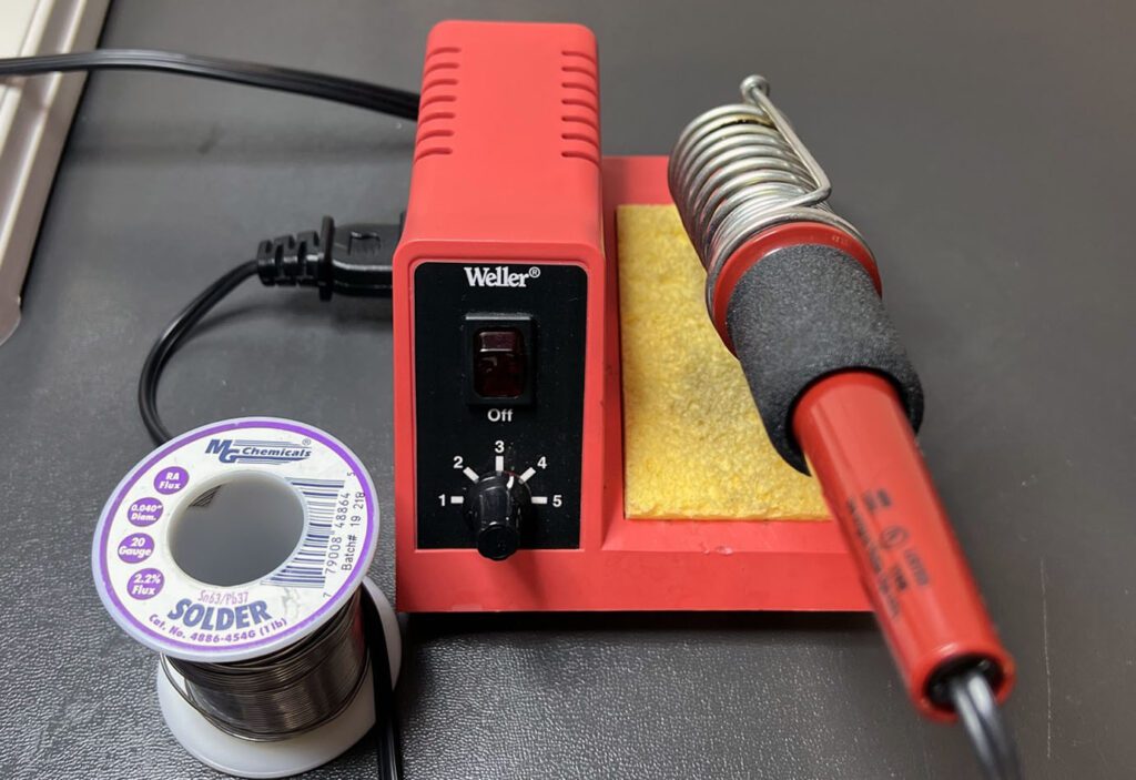
And while we’re on the subject of solder, I recommend investing in a good-quality soldering station for bench work. A variable heat function is helpful because it allows the user to use just the right amount of heat for the application.
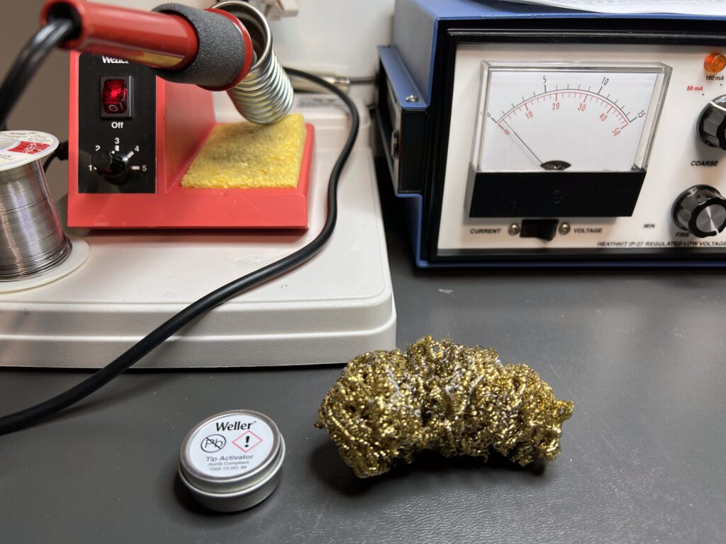
The tip is of course a critical part of the soldering iron. With use, the tip deteriorates. It is good practice to replace the tip from time to time. Before doing that, however, try a tip “tinner and activator” (one is show in the photo above). This product is used to regenerate an oxidized tip, thereby extending its useful life. Weller makes one product of this type; there are others as well. The brass sponge shown in the photo is also helpful in keeping the tip clean during use.
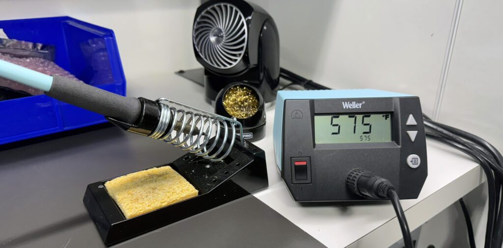
When soldering, the objective is to use enough heat to provide for a good electrical and physical connection, but not so much that it may damage the component. A soldering station with tip temperature readout (as shown above) is very helpful. The optimum tip temperature varies depending on the tip used and other factors; experience will dictate the best approach. For example, when soldering small components, such as resistors and semiconductors, a tip temperature of 575º F may be used. When soldering larger components, such as 2 W resistors or plug-in connectors, a temperature of 600º F may be used. For still larger components, such as PC-mounted transformers, a temperature of 625º F may be used.
Some soldering stations include an auto-off feature that turns the soldering iron off after some period of time (or reduces the tip temperature) as a way of preserving the tip. Everybody has had the experience of using a soldering iron and then being distracted and finding later that the iron has been active and unused for hours.
Also, make sure to provide proper ventilation whenever soldering.
Wire and Cable
Hookup wire is essential to almost every electronics device. However, it is not always given the attention that it deserves. There are, of course, a wide variety of wire types to chose from but the most basic division is stranded or solid.
I used solid #22 hookup wire for years. It is easy to work with and inexpensive relative to stranded wire of the same size. More recently, however, I have moved exclusively to using stranded #22 for most jobs.
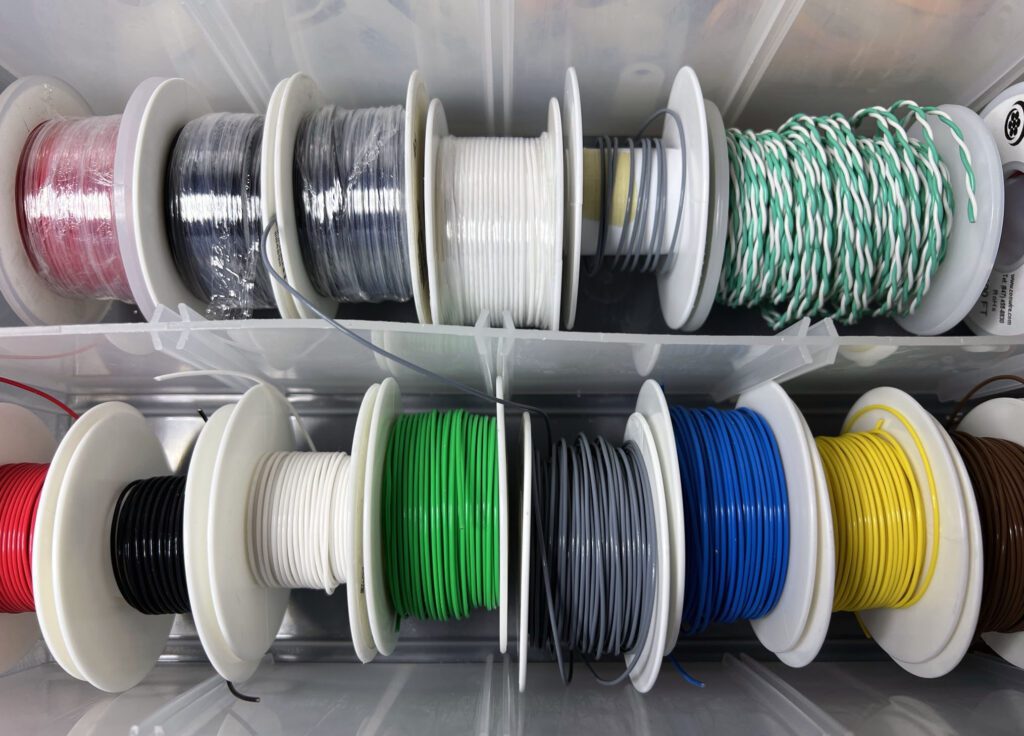
Hookup wire is available in a variety of colors, which is helpful for assembly and later for troubleshooting. The use of wire colors can make a small system self-documenting, which is a time-saver if work needs to be done on the system at a later date. For more complex systems, it may be helpful to prepare a wire color log that maps the various colors to specific functions. An example log is provided here.
Be careful to check the rated voltage of the hookup wire, particularly if you are working with high voltages.
The selection of cables, where more than one conductor is enclosed in an outer jacket, is equally important and deserve careful consideration. Characteristics include the number of conductors, wire size, color (jacket and conductors), shielding, distributed capacitance, thickness, weight, etc.
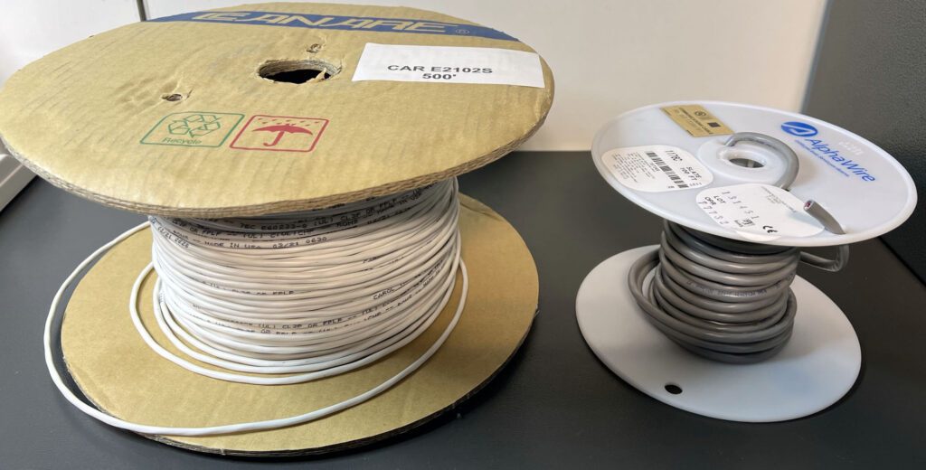
For the 1970s radio studio, I needed to make hundreds of connections. I wanted, therefore, to find a twisted pair shielded cable that performed well and was easy to work with. I began the search by ordering small quantities of audio cable that looked promising. After some experience working with the samples, I then selected one from the group.
Ordering in large quantities is always more economical than in small quantities, but accurately estimating the amount of cable needed for a large job is difficult. Ordering in 1,000-ft increments is usually a reasonable tradeoff.
A related consideration is termination. Some connectors and terminals are easier to work with than others. Often, the cost difference is small and well worth the expense if a number of connections are required. Here again, ordering a sample of several connectors is often time well spent.
However you configure your work space, make sure it provides a comfortable and efficient layout. Time spent in the shop working on hobbies should always be fun!
Equipment refurbishment certainly does not require all of the instruments shown above. A subset will suffice.
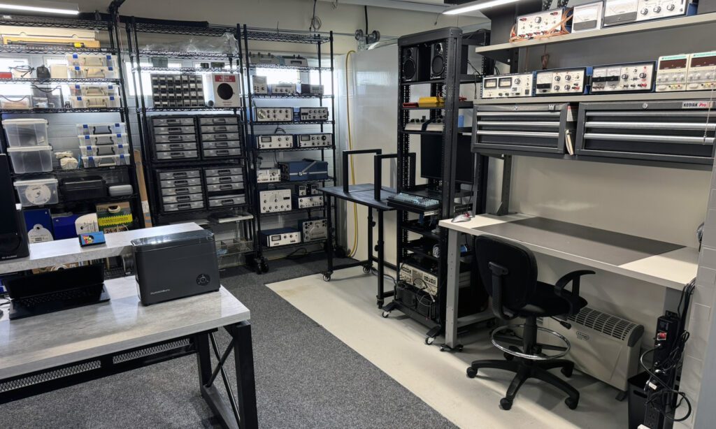
My workspace has evolved over the years and grown as the space available has expanded. The current setup is shown in the photos below. The expansion was made possible by a reduction in the number of cars that needed to be in the garage as our daughters went off to college!
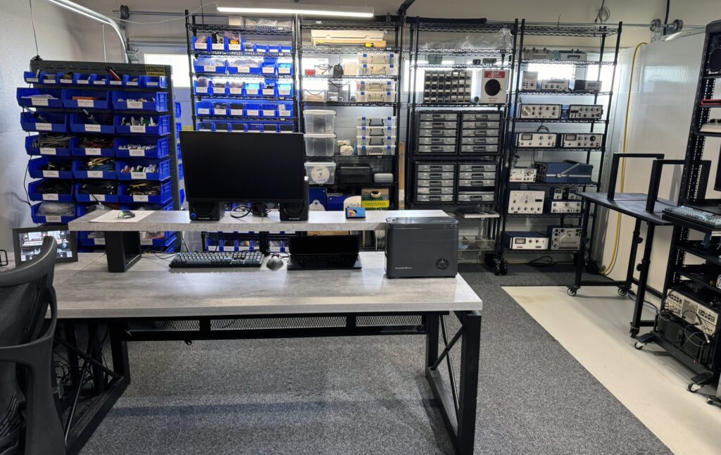
With the increased available space, the workshop doubles as an office.
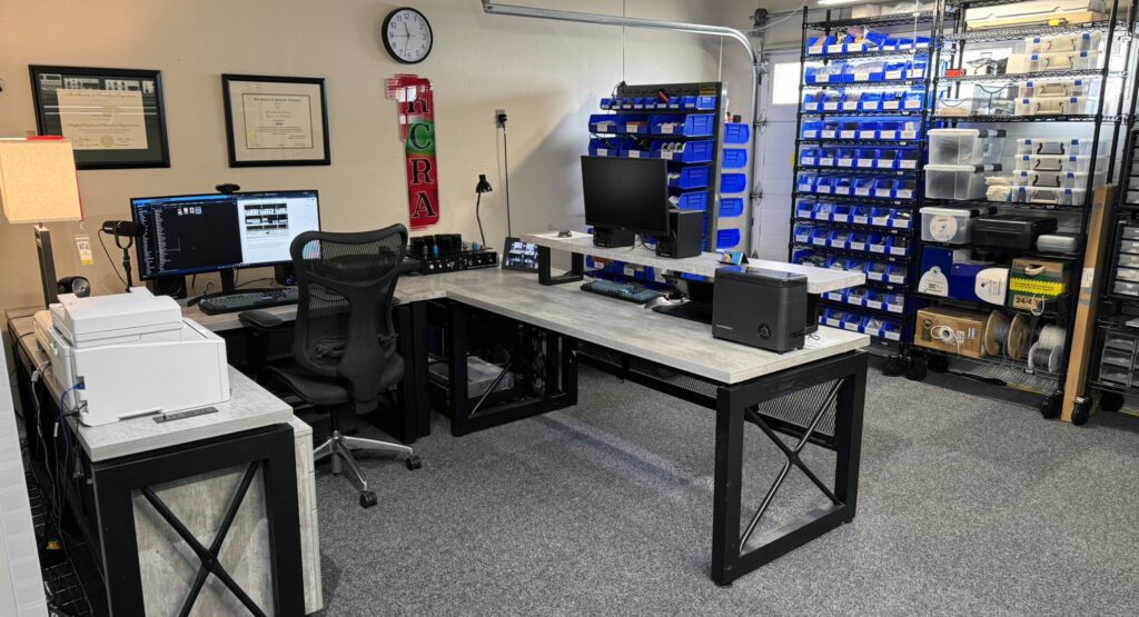
The same general principles described above for the previous workspace setups are followed in the current arrangement.
The effort to build up a test bench consisting almost entirely of classic Heathkit test gear from the 1970s taught me (maybe just reminded me) that an electronic circuit that is designed well, uses high-quality parts, and is carefully constructed will perform useful work for a very long time.