Ampex AG-440 Tape Machine Restoration
The Ampex AG-440 is a classic professional machine that was popular back in the 1970s and 80s. This restoration project takes a neglected and worn reel-to-reel recorder and restores it to like-new condition. The effort is documented below, from day one until completion.
The Ampex AG-440 was a mainstay of radio station operation, used in countless facilities large and small. Rugged and durable, it was perfect for use in a radio station where it had to perform correctly all the time. The recorder is a marvel of mechanical and electrical engineering. Like other pro reel-to-reel recorders of its day, it accommodated 10.5-inch and smaller (e.g., 7-inch) reels. Owing to the use of a number of solenoids, motors, and other electro-mechanical devices, full remote control was possible. This was a basic requirement of radio station operation.
The AG-440 was expensive, but gathered a loyal following over the years. It was available in a variety of configurations, from full track mono to stereo to multi-track (up to 4 channel) operation.
Background – The Project Begins
Back in the 1970s and early ’80s I operated multiple AG-440 reel-to-reel machines, first at a college radio station and later when I was chief engineer for an AM/FM station in Northern California. I loved the machine. It was easy to use and reliable. As the 1970s radio studio project began to take shape, I knew that I had to have an AG-440 to round-out the equipment list. The search on eBay took more than a year. While a number of good candidates were offered for sale during this time, shipping was a challenge due to the size and weight of the deck and associated electronics. My original goal was to find an AG-440 in its distinctive roll-around cabinet. That being the case, I was limited to “local pickup.” I finally gave up on acquiring the Ampex cabinet and when I found a deck in what appeared to be relatively good condition, I bought it. Separately, I purchased three of the AG-440 preamps; I only needed two for stereo but wanted to have spare parts in case they were required.
I knew from the eBay listings of the deck, and especially the preamps, that some serious work was going to be required to return this classic machine to serviceable condition. I had a good feeling for the amount work that would be needed, having restored a lot of professional audio gear over the years. I knew that it would take a number of weeks, and it would be expensive. As a rule of thumb, I plan on a 4x restoration budget; i.e., if it costs $100 to acquire the hardware, I will probably spend $400 to restore it. We’ll see how it goes.
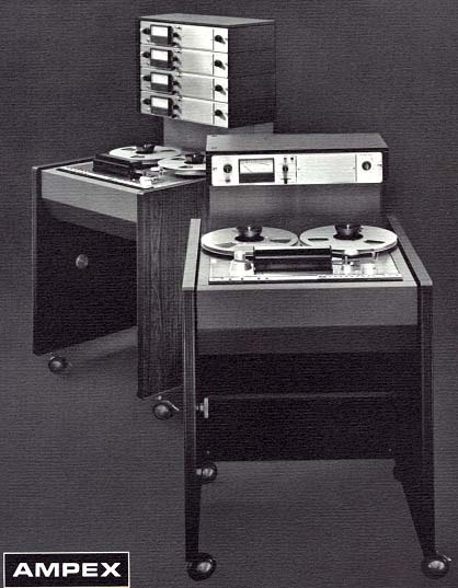
The photo above is from an Ampex catalog, circa 1980. Shown are the one track and 4-track versions of the tape machine.
Day 1 – Assessing the Condition of the Preamplifiers
The preamps arrived today. The eBay listing included photos of the preamps from a number of angles. As such, I wasn’t surprised by what I found. Clearly, they had been neglected for a very long time. The top and bottom covers were missing, which made the dust and dirt problem more pronounced. As stated above, three preamps were purchased on eBay. Two of the three are in OK condition; the third is in rather bad shape (probably fixable, but a challenge).
The initial inspection of the preamps showed that all components were in place and that no modifications appeared to have been made over the years. I was encouraged by that. Initial work will focus on cleaning the chassis and front panel. Also, top and bottom covers will need to be reproduced. That task will fall to the team at Protocase, which I have used extensively for various projects documented on this site.
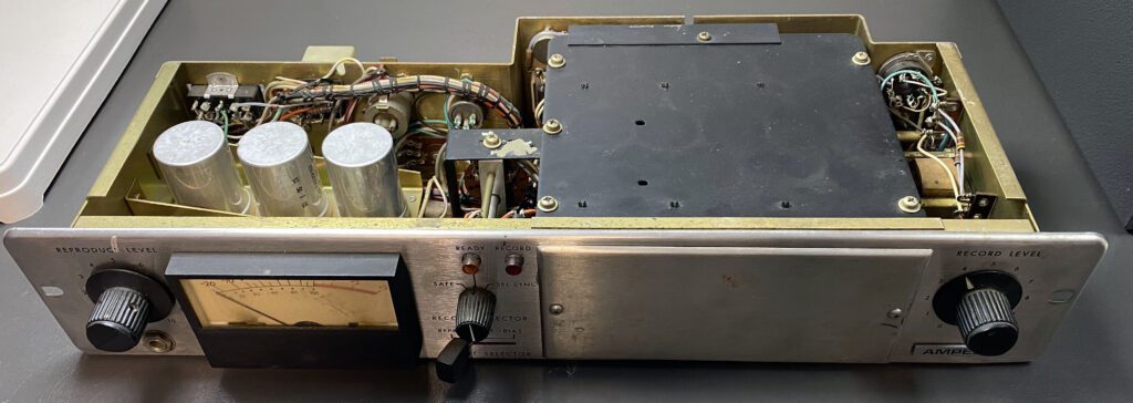
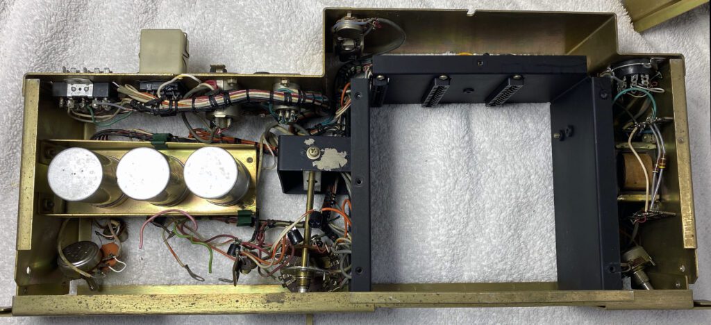
There is some rust damage on at least one of the chassis. That will be hard to fix without completely disassembling the preamp. In addition, some of the XLR connectors show signs of rust, which can be seen in the photo below.
The preamp PCBs are contained in a closed housing (the black box that can be seen in the photo below).
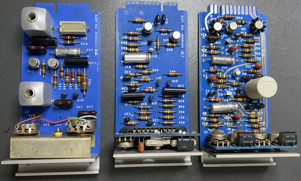
The good news with regard to the preamps is that the circuit boards (three in each chassis) are in very good shape. There are no indications of previous failures or maintenance.
Interestingly, the PCBs have traces on both the top and bottom, which was unusual for hardware built in the 1960s and early 70s. I have no doubt that a complete realignment will be needed on the cards, but at least they are in good shape going into the process.
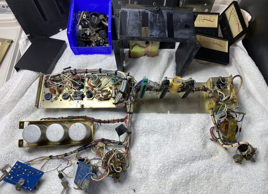
The first of the three AG-440 preamps has been disassembled to gauge the work required to restore the unit to like-new condition. The photos below show the extent of disassembly that is practical without completely breaking down the chassis. Such decisions always involve trade offs.
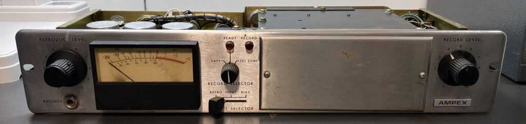
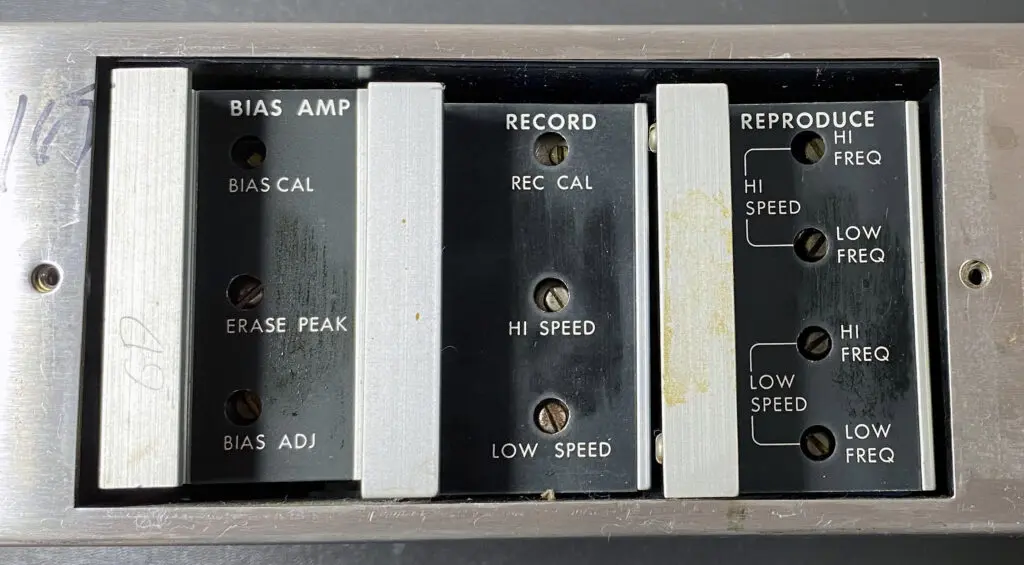
In this case, the chassis itself is in fairly good shape and the internal electronics look OK. With the front panel removed, it was possible to do some aggressive cleaning. Fortunately, the efforts paid off. The front panels look rather good now (not perfect, but acceptable).
Since I purchased three of the preamplifiers, I am confident of getting at least two of the units working without too much effort.
This project is all about the mechanics (and appearance) of the machine. The internal electronics is the easy part. Cleaning and repairing the mechanical and electro-mechanical elements are the real challenge.
Day 2 – Work on the Preamplifiers Begins
The transport deck is due to arrive soon. Until that happens, I will continue to work on the preamps. As mentioned above, I bought three preamps. I only need two for stereo, of course, but figured that the spare parts would come in handy. My original concept was to identify the preamp that was in the worst shape and part it out. After identifying that preamp, I thought it might be worthwhile to try and refurbish all three.
The more I began to get into this preamp the more disappointed I was with the condition of the unit. None of the three preamps were in what I would call good shape, but this one was a real challenge. The insides were coated with dust and dirt (and even some bugs). This was all the result of neglect. The top and bottom covers had been removed and wherever these preamps had been stored for the past few decades was far from an ideal environment. Frankly, it amazes me how someone could allow high quality gear like this waste away. Anyway, enough complaining.
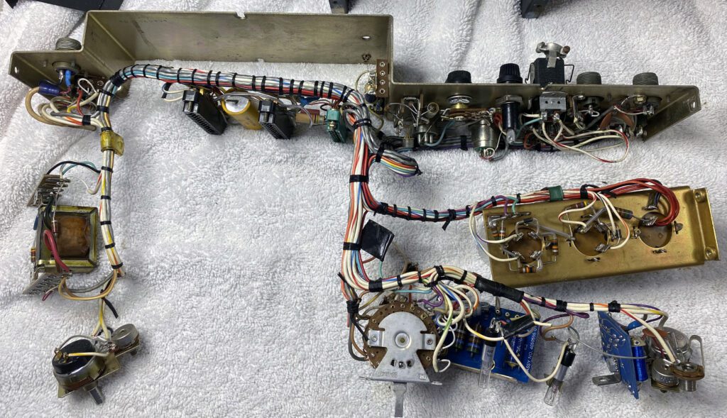
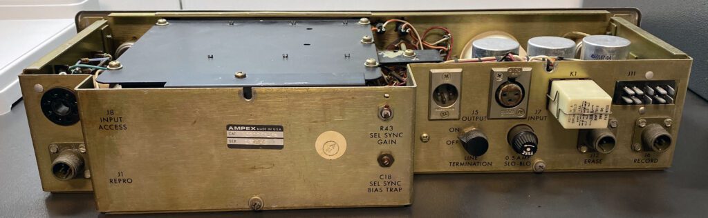
The condition of the third preamp was such that I had nothing to lose. So, I went for broke. The photos above show the extent of disassembly. To return the chassis to an acceptable state, it will be necessary to have it sandblasted and then powder-coated. The rear panel is another challenge. Additional disassembly will be needed, including disconnecting a number of connectors in order to free-up the back panel. Once powder-coated, the back will need to have the lettering silkscreened. This will be expensive, but it is the only way to make the preamp look like new. With these considerations in mind, my current plan is to do what I had originally intended to; namely, use this preamp for parts and not try and return it to service.
Day 3 – Preamplifier Work Continues
The focus today was on cleaning up major elements of the preamplifiers and compiling a parts list for components that are likely to be replaced. As a starting point, the front panel potentiometers will be replaced. They are sealed types that cannot be cleaned. And, there is no better time than now to replace them. An inspection of other components, notably electrolytic capacitors, yielded short list of targeted replacements.
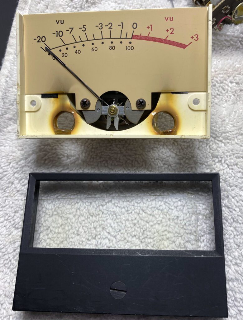
In order to remove the front panel of the preamplifier, the VU meter must be removed. The design of the VU meter facilitated easy maintenance. The faceplate is removed with two screws and the window is a piece of removable glass. Many meters have a plastic view port, which is difficult to clean because solvents will damage the plastic. The glass element is ideal since it can be easily removed and cleaned. With the view port removed, a light coat of paint (black satin finish) was applied to the faceplate.
The photo above shows the meter disassembled prior to any work. Discoloration of the VU scale plate can be seen. Scratches are also visible on the faceplate. The two holes at the bottom of the meter assembly are for pilot lamps. Note that over time, heat from the pilot lamps has discolored the meter housing.
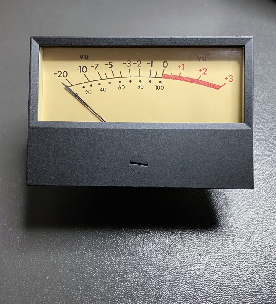
The photo above shows the VU meter after refurbishment. It looks brand new. The VU meters were particularly easy to bring back to like-new condition. That was an unexpected, and welcomed, surprise.
Day 4 – Assessing the Condition of the Transport Deck
The AG-440 transport deck arrived today. I had set my expectations to a rather low level, given the experience with the preamps. Fortunately, I was pleasantly surprised. The front of the transport is in remarkably good condition. A thorough cleaning is probably all that will be required. The hardware on the rear side is dusty but otherwise looks good overall. The two reel motors turn freely and the brakes work. The capstan motor also turns freely. The moment of truth, of course, will be when the deck is pulling tape. However, preliminary indications are good.
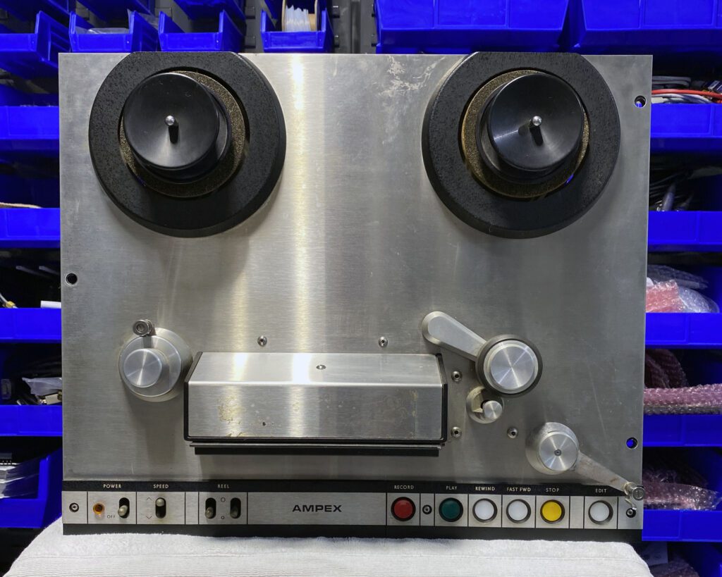
It may be possible to get the front of the deck looking new without removing major components. We’ll see how that goes. I was pleased to find that the deck included the reel caps. I hadn’t noticed them in the eBay listing. That saved me some money, and another visit to eBay.
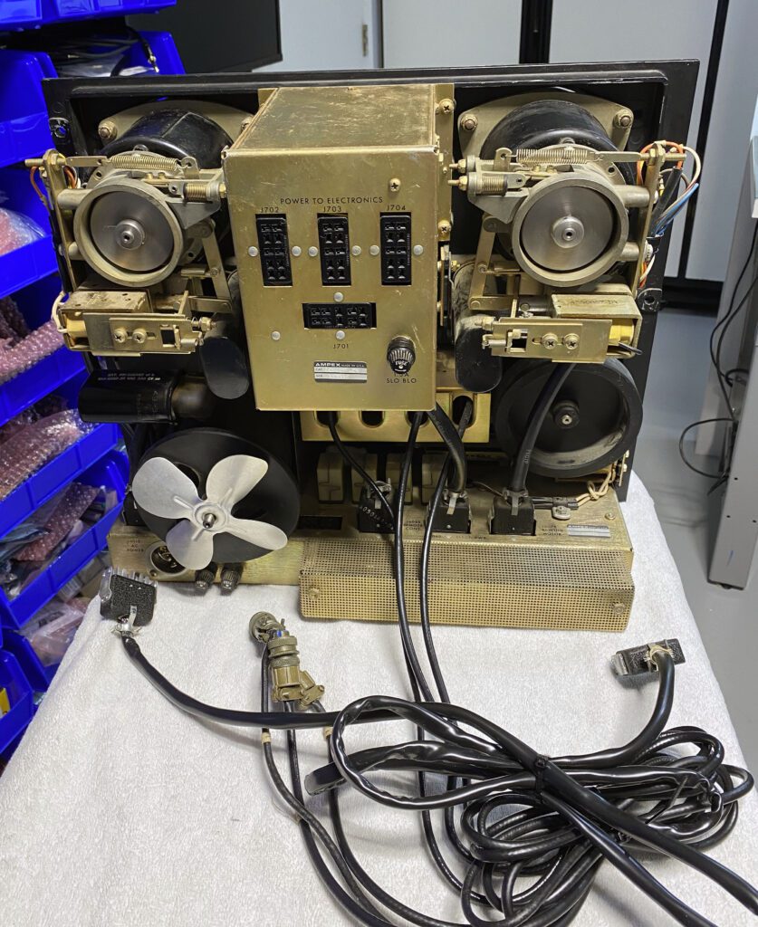
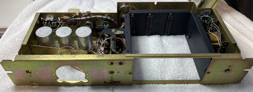
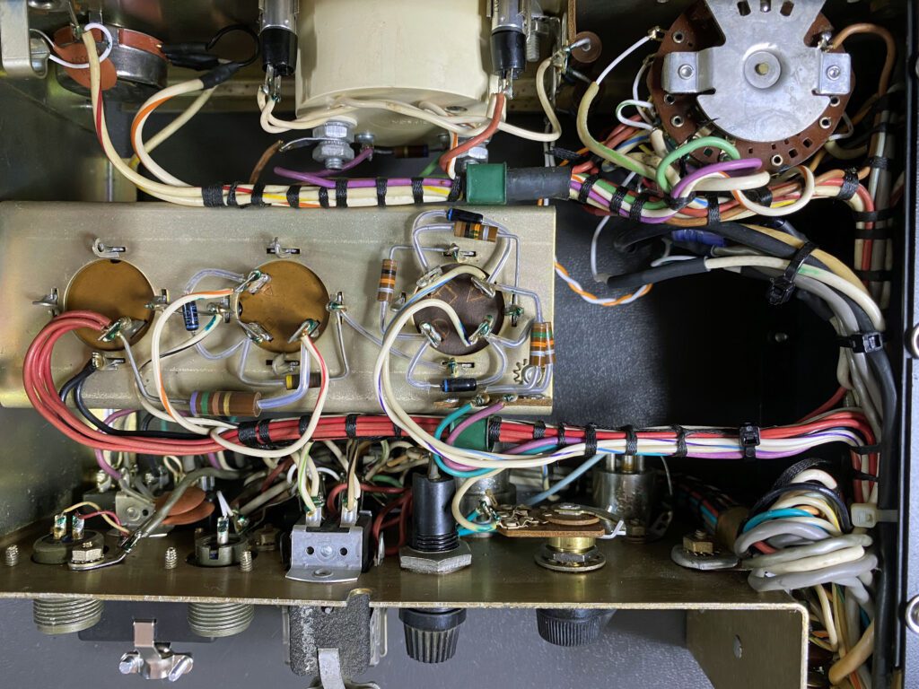
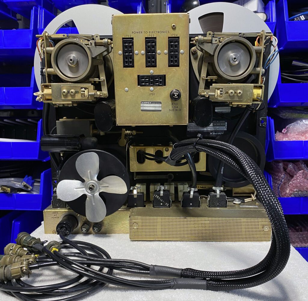
The photo above shows the rear of the transport. This picture was taken before a once-over cleaning. All things considered, the components look OK. All parts appear to be in place. I may be able to return the transport to service with little more than a good cleaning and inspection. Also, mechanical adjustments will certainly be required. Fortunately, the Ampex user manual has detailed instructions for mechanical adjustments.
It is evident that a number of electrical connections are made between the transport and the preamps. Cables are provided for the tape heads (they are hard-wired at the transport). Power for the preamps and the optional remote control use Cinch Jones connectors. Fortunately, these are available from multiple sources, so this should not present a problem. Also, the power cord was not include with the unit. It is a specialized connector but is still available commercially (Hubbell HBL7484).
Day 5 – Cleaning the Transport
The focus of work has shifted to cleaning and checking the AG-440 transport deck. After a thorough cleaning the transport hardware is starting to look very good. Near new, actually. When I purchased this transport on eBay I was concerned about how much work might be required to return the unit to good condition. My fears were unfounded. There may be issues that I haven’t discovered yet, but so far so good.
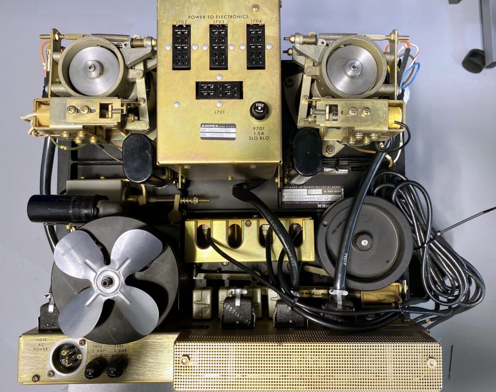
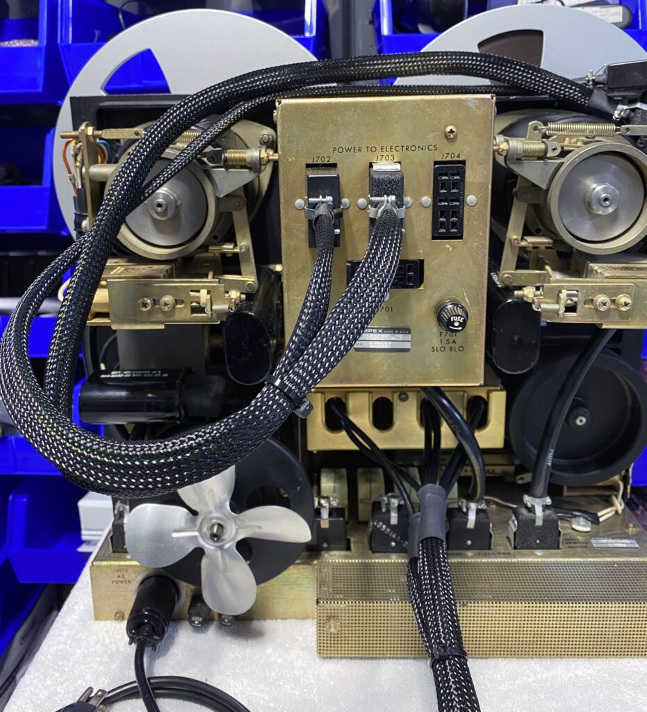
The photo above shows the transport rear view. Cleaning and checking provided an opportunity to compile a parts list of items that I need to acquire to keep the project moving forward. Not much so far, fortunately.
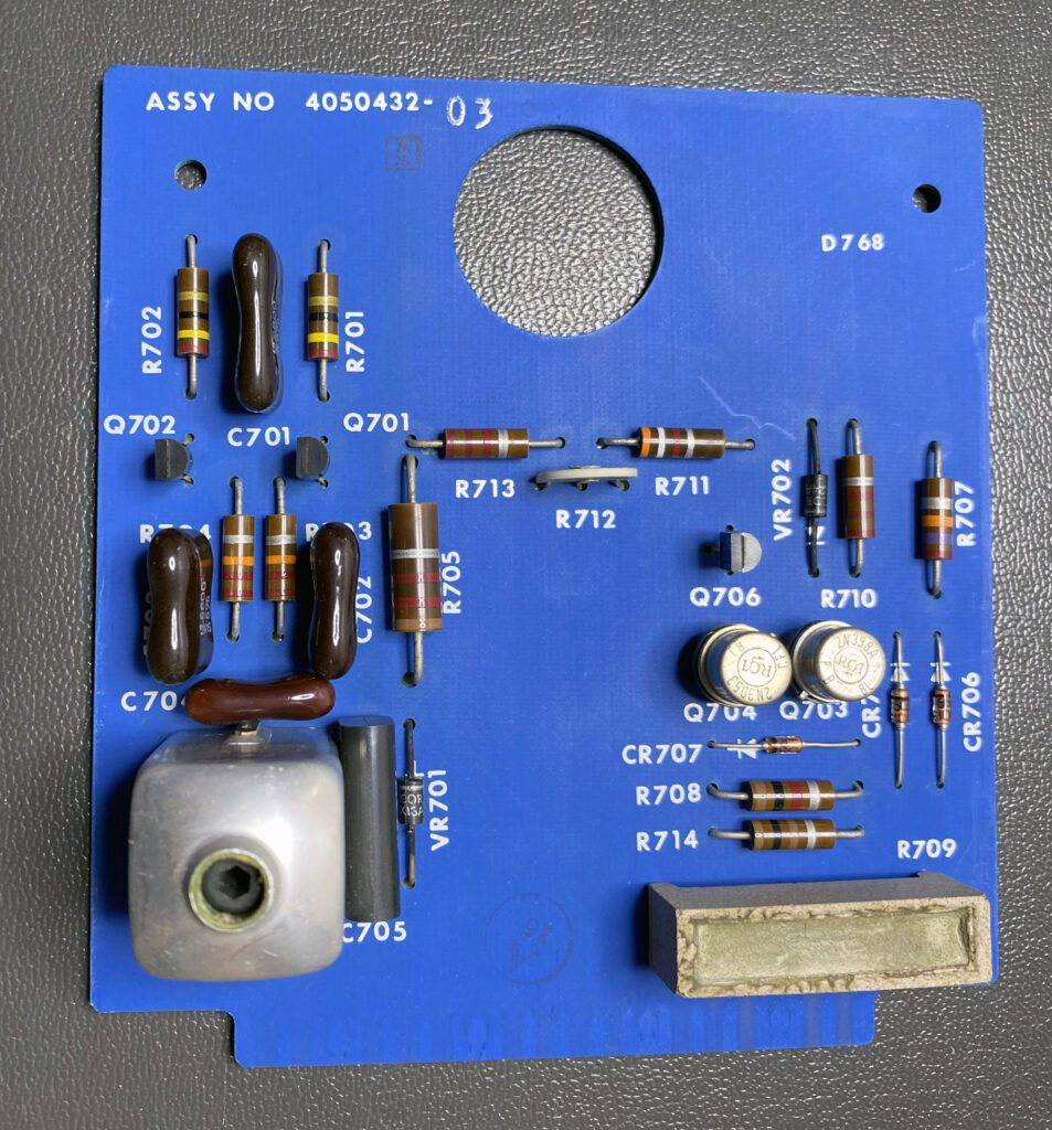
The photo above shows the bias oscillator PCB. All of the circuit boards in the preamplifiers and transport are in exceptionally good condition. There is no evidence of past failures or rework. I may still have problems, of course, when I power up the system and begin to run performance tests. That’s for another day, however.
The transport control chassis was inspected and found to be in good shape. I have ordered a few replacement parts, not because they have failed but rather as a precaution. Within the deck (and the preamplifiers too) there are some very old large-value electrolytic capacitors. While I have the machine disassembled, it makes sense to replace those components.
Day 6 – Transport Electronics
Most of the electronics for the AG-440 transport are contained in a single chassis at the base of the deck. After cleaning and inspection, a short list of components were identified for replacement.
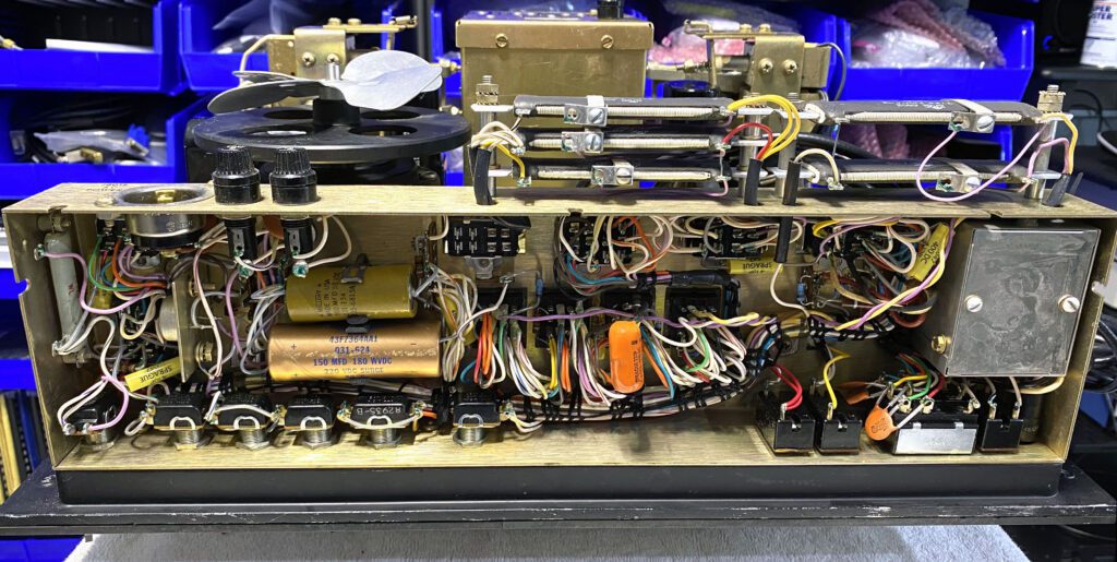
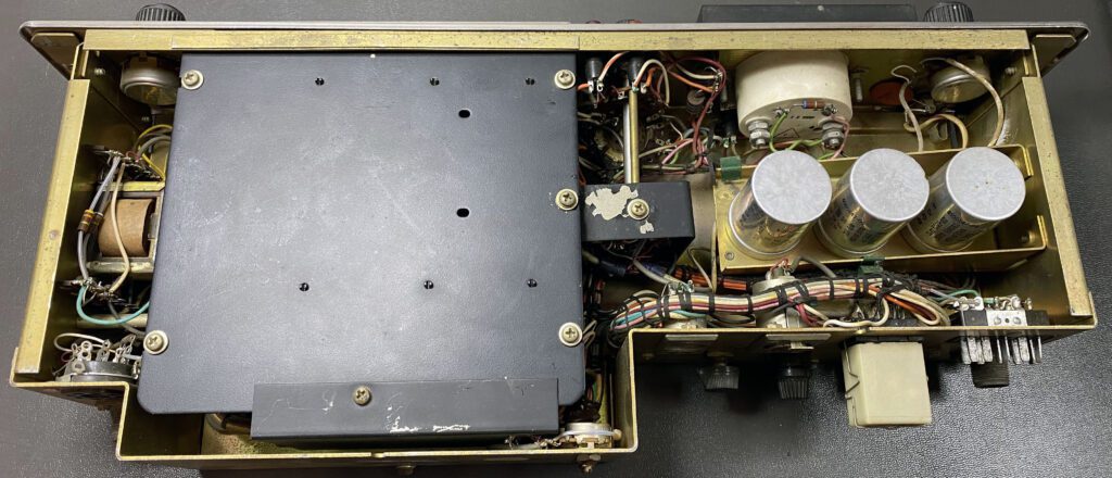
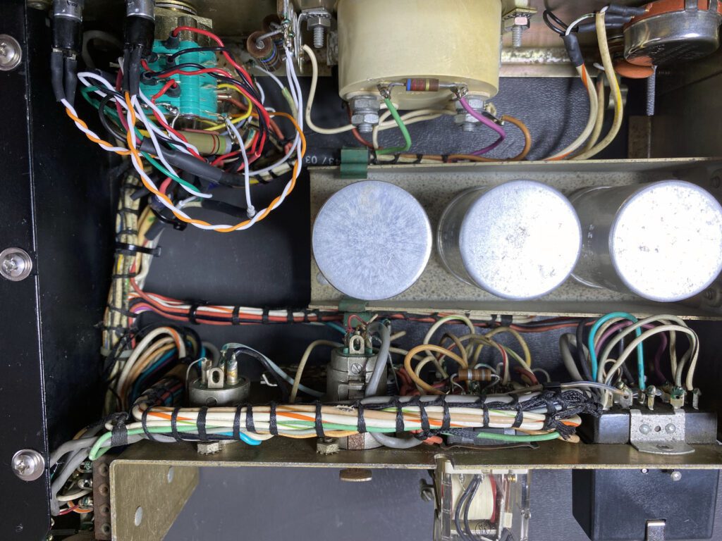
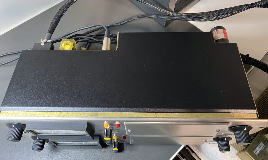
The photo above shows the control chassis before any work was done. Note the two large paper-covered electrolytic capacitors. Those will be replaced, along with a film capacitor that appears to have been installed during repair at some point. The installation job was not too impressive, so it will be redone.
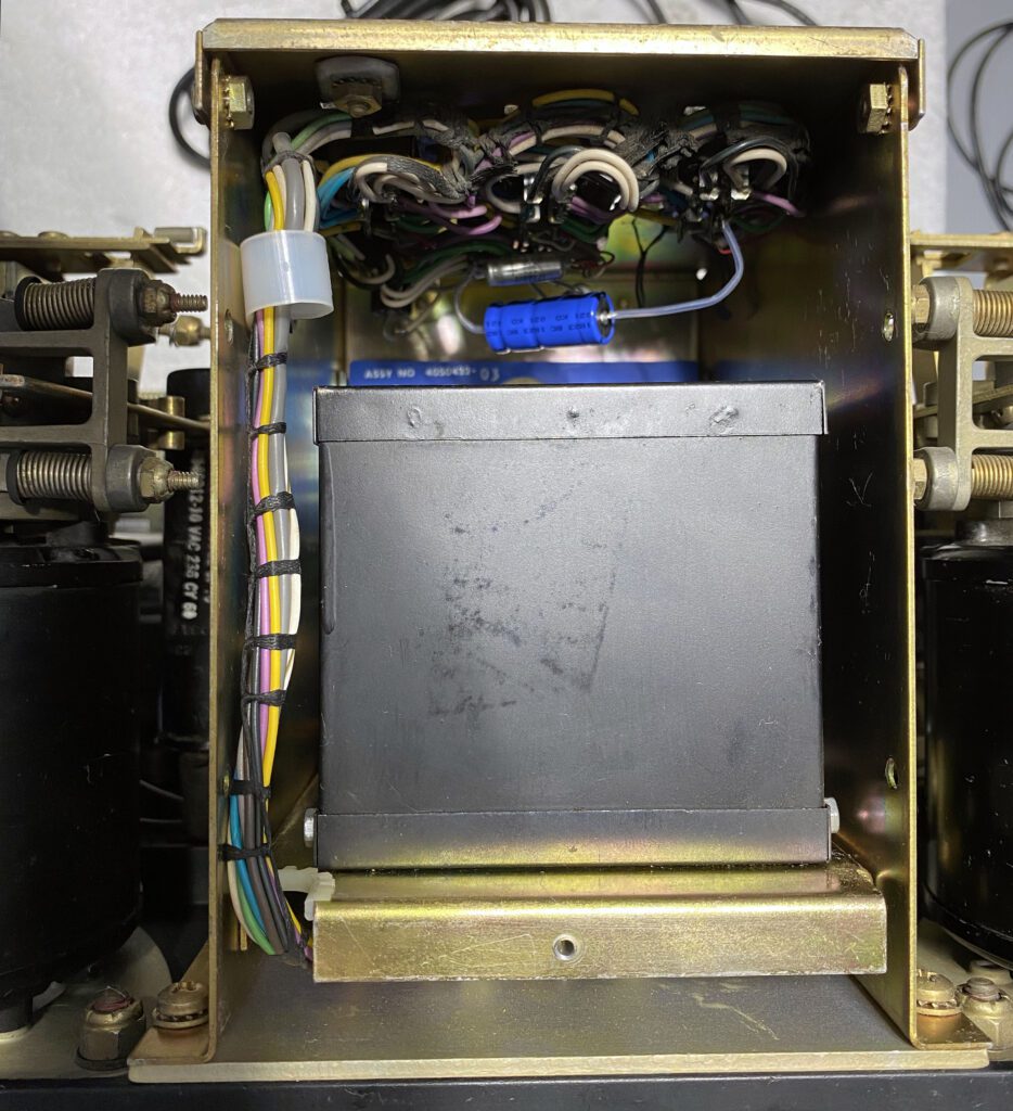
The power supply for the preamplifiers is contained in an enclosed chassis on the transport (see the photo above). No issues were found with the preamplifier power supply. The unit was cleaned and inspected. One of the two cables required to power the preamplifiers was supplied with the transport deck. The necessary connectors have been ordered to build a second cable.
Day 7 – Transport Front Panel
Having completed initial work on the rear of the transport, the focus now shifts to the front of the machine. As mentioned previously, the front panel and associated elements are in generally good condition. The only obvious flaw is that one of the cork turntable (reel) pads has pulled away from the housing. After an attempt to reattach the pad using an adhesive, which was not entirely successful, I found new (remanufactured) turntable pads for sale from a vendor in Seattle (Full Track Productions). I purchased a pair. I might or might not replace both pads; we’ll see how it goes. In the meantime, I have cleaned the turntable in preparation for the new pad.
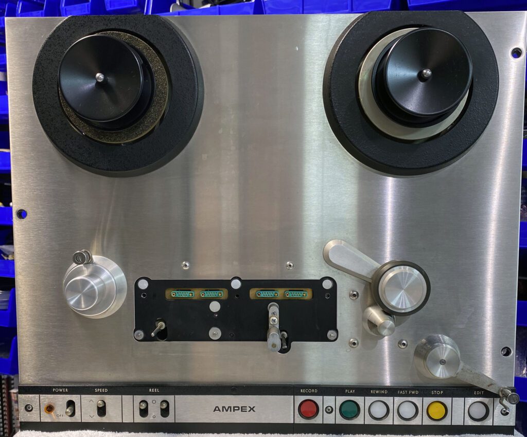
The photo above shows the transport front panel after a thorough cleaning. The head assembly was removed to gain access to all areas of the machine. The transport face plate is in very good condition, with no visible flaws. The switch panel in the lower portion of the machine is likewise in good condition.
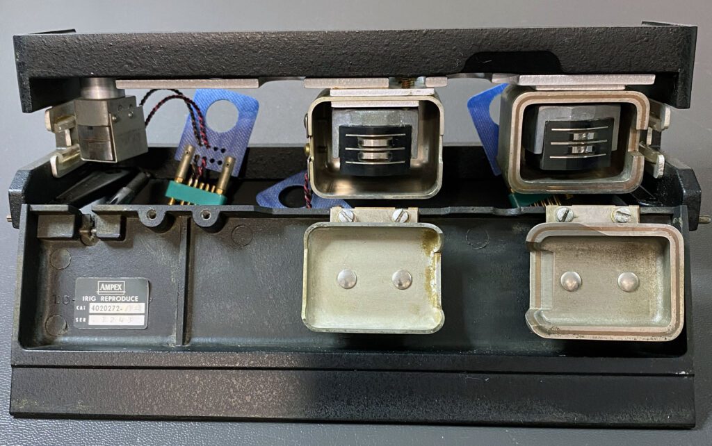
The photo above is a close-up of the tape head assembly. The heads look good, although a determination of their condition will ultimately be made through performance tests. The head assembly was cleaned and the heads inspected closely. No additional work is planned on the head assembly at this time.
Work on transport will now go into pause mode pending receipt of parts; specifically, the turntable pads and ac power connector. In the meantime, I will focus on the preamplifiers.
Day 8 – Preamplifier Work Continues
Initial repair on the first of two preamplifiers was completed today. As mentioned above, a thorough cleaning of the front panels returned them to good condition. Not perfect, but good. Options were explored for remanufacturing the front panels, but the decision was made to use the originals. It would have been cost-prohibitive to refinish the existing panels. Producing new panels would have been much less expensive; however, matching the original look would have been difficult.
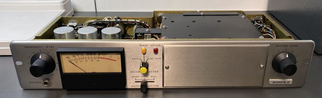
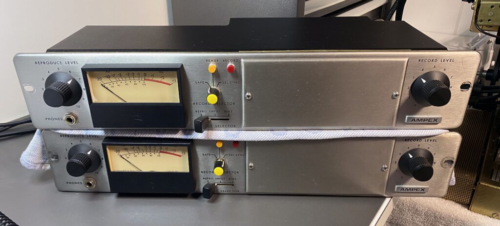
The photo above shows the preamplifier front panel after reassembly. It turned out very well. New knobs helped to freshen the look, and with the the refurbished meter, the unit looks great.
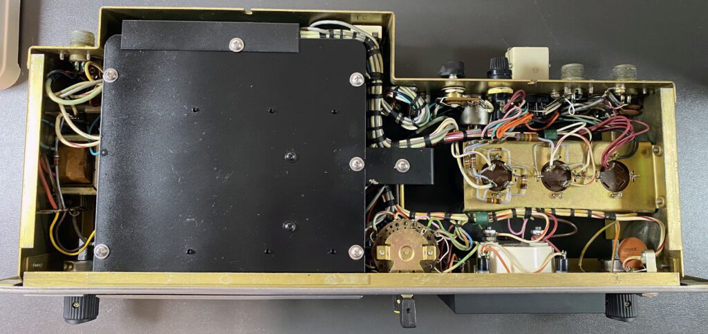
The photo above is a bottom view of the preamplifier. After a thorough cleaning, the internal wiring and components look quite good.
Top and bottom panels for the chassis are being produced by Protocase. They will be installed when completed. No additional work is planned on this preamplifier until it is mated with the transport, at which point it can be powered up for testing.
Day 9 – Initial Preamplifier Work Completed
Initial repair on the second preamplifier was completed today. This one was a bigger challenge than the first. The major issue was the SAFE / READY / SEL SYNC switch, which had been damaged beyond repair. The original switch had suffered some very poor maintenance in the past. A botched repair job apparently resulted in half of the first wafer of the switch (the one closest to the front panel) being broken completely away. Needless to say, this necessitated replacement of the entire assembly.
The three-position rotary switch is not unusual, except for its physical implementation. The front and rear wafers are separated by about 3-inches. Matching this design in a modern device is difficult. One option entertained (for a moment) was to purchase another AG-440 preamplifier and use it for parts to fix the damaged switch. This would have been sketchy at best. The solution, then, was to replace the damaged switch with a new 6 pole 3 position Electroswitch device. Given the physical design of the new switch, it was necessary to extend most of the wires from the rear wafer in order to reach the new device. The photo above shows the preamplifier chassis top after the repair job. The new switch can be seen in the upper left hand corner of the photo.
The photo above is a bottom view of the preamplifier chassis. The end result was quite good. This is a far better solution than trying to fix the old switch. As an aside, I had hoped to replace the broken switch wafer with one from the the third preamplifier that I had purchased for parts. As misfortune would have it, that switch was damaged as well.
Work on both preamplifiers has been completed for now. The third preamplifier will be set aside and used for parts as needed.
Day 10 – Replacing the Turntable Pads
The focus of work has returned to the transport deck. As mentioned above, replacement of at least one of the turntable pads was necessary. I ordered a pair of replacements from Full Track Productions in Seattle. The pads are an exact replacement for the originals. And they look great.
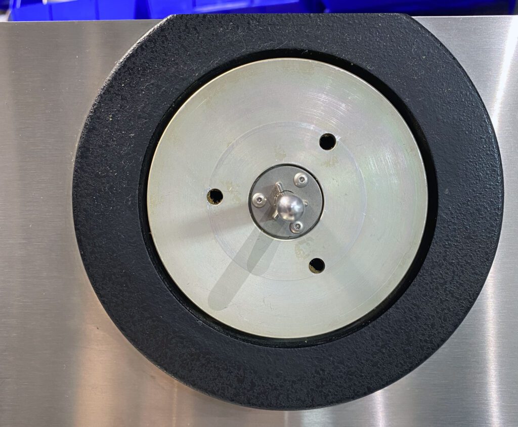
The first step in replacing the pads was to remove the old ones. This was easier said than done. The old cork pad quickly separated from the adhesive, most of which remained on the turntable. Getting it off was a real challenge. A combination of scraping with a razor blade and then cleaning the residue with acetone did the trick. Be very careful with acetone. If you get it on the painted rim of the turntable, the paint will come off. And use proper ventilation and gloves. The photo above shows one of the turntables after cleaning.
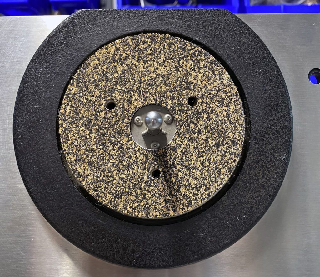
The pads were reattached to the turntable using 3M #77 spray adhesive. This is really good stuff. Follow the instructions provided by 3M (and in this case by Full Track Productions). The photo above shows the completed project. It’s a big improvement. Since I had good luck with one turntable, I replaced the other as well.
Day 11 – Ready for Testing
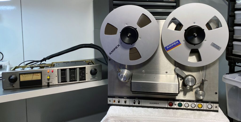
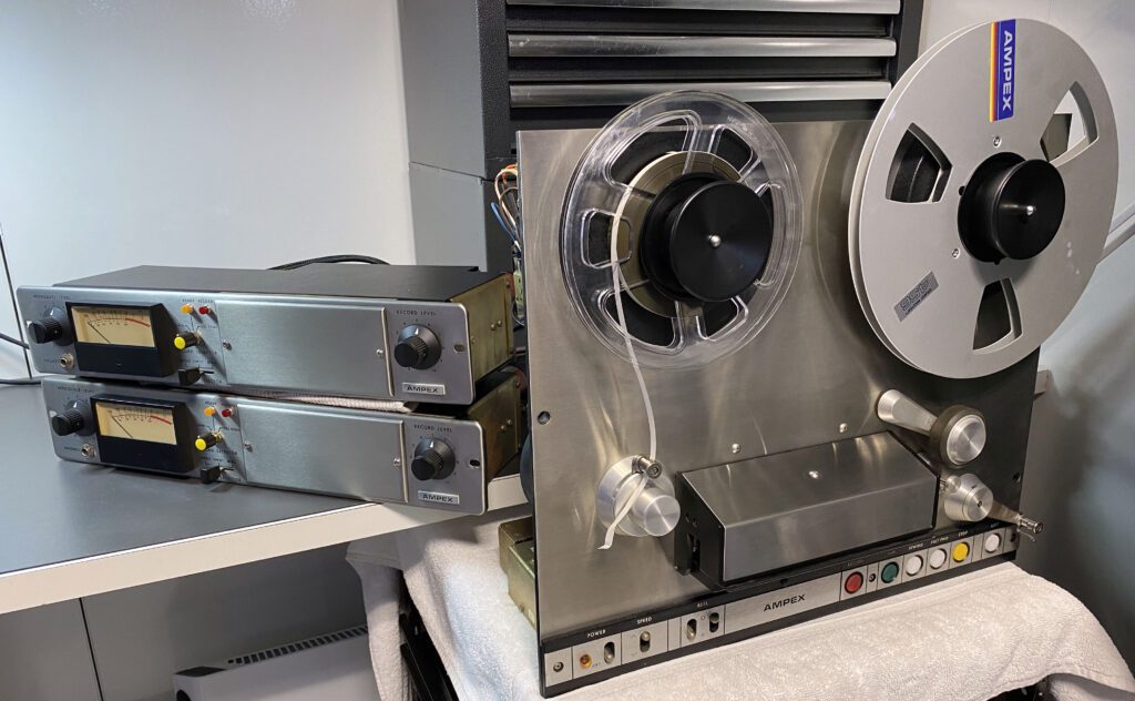
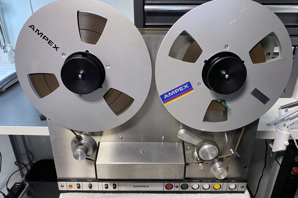
The transport is ready for testing. An empty 10.5-inch take-up reel and a reel of Ampex 406 tape were purchased on eBay and loaded up.
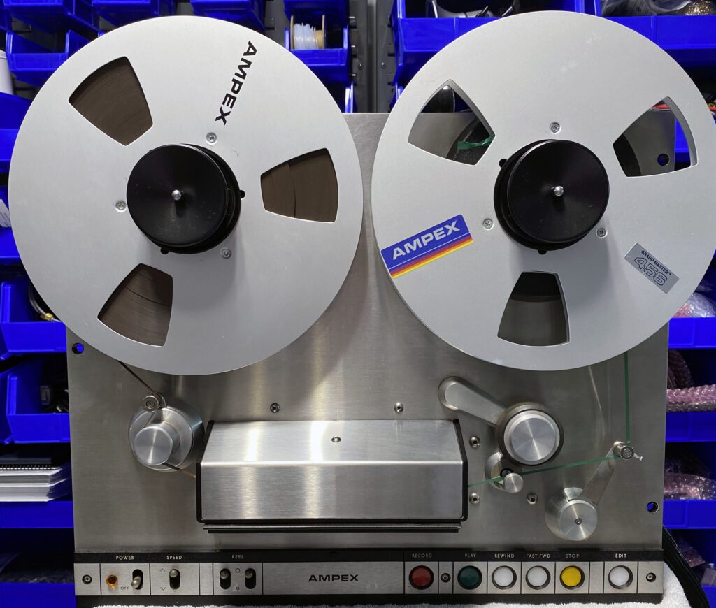
It can be seen in the photo above that the AG440 is looking quite good. The ac power connector arrived, which made it possible to power-up the machine. The Hubbell HBL7484 fit perfectly.
A recently discovered issue is the tape head cables. It should have been obvious to me from the beginning that cables for only one set of the stereo tape heads was brought out of the head assembly. (Unfortunately, I missed that completely.) The heads on the machine are stereo, but the block is wired for mono. So, additional connectors are required. Fortunately, exact-replacement “Cannon” connectors are available from multiple sources. The part numbers are Cannon MS3106B10S-2S (one contact plug for the erase head), Amphenol MS3106A10SL-4S (two contact plug for the record head), Amphenol MS3106A10SL-3S (three contact plug for the reproduce head), and Amphenol 97-3057-4 (cable clamp, one for each of the 10SL plugs). Note that the same cable clamp is used on the record and reproduce head connectors (Cannon 10SL type). For the erase head, a smaller cable clamp is used. It it is the Cannon M85049/41-3A. These devices are available from multiple sources, although often on a special-order basis.
The initial power-up configuration is shown above. One preamp was connected and power applied. The transport functions work, although Rewind and Fast Forward are much slower than normal. The preamp Record function appears to work correctly but Play does not. These issues are not unexpected. I will work through them one at a time, beginning with the transport.
Day 12 – Cleanup Work on the Preamplifiers
Work is proceeding on the replacement top and bottom chassis covers for the two preamplifiers. As noted above, all but one of the covers were missing from the units purchased on eBay. It was necessary, therefore, to remanufacture those pieces. Duplicating the covers was not a simple task, so rather than attempt to design them myself, I engaged the Protocase team to take the one sample cover that I had and produce replacements. The top and bottom covers are mirror images. Also, I opted for a black satin powdercoat finish rather than attempt to match the finish of the original.
The AG-440, as purchased on eBay, did not include a cabinet. Since the machine, obviously, needs a cabinet of some type, three options were entertained: 1) mount the machine in a standard vertical rack, 2) have a local cabinetmaker replicate the Ampex cabinet, or 3) do something else. I opted for #3. While duplicating the Ampex cabinet was an attractive solution, it would have been expensive and the space requirements for the finished product would have been substantial (which is a problem given the limited space in the 1970s studio). Off-the-shelf cabinets were considered but it was difficult to find one that accommodated the AG-440 in a space-efficient way and facilitated convenient operation. The search for a solution continues.
While these activities are underway, today I finished checking the reel and braking tensions on the transport against the specifications contained in the Ampex maintenance manual. I was pleased to see that all of the parameters were within specification. The Fast Forward and Rewind functions were previously observed to be slower than normal. The root problem was not the transport tensions but rather the tape itself. I had purchased a roll of used tape to check operation of the transport. The tape had deteriorated to the point that significant oxide deposits accumulated on the tape guide paths, which increased friction and thus slowed the Fast Forward and Rewind functions. Since the transport checks have been completed, I will order a NOS roll of tape for performance measurements.
Day 13 – Wired for Stereo
Work today focused on the cabling that connects the AG-440 transport to the preamplifiers. While the tape heads on the AG-440 purchased on eBay were two-track, the transport was wired for mono. So, additional cables were required to enable stereo operation.
The cables supplied with the machine are typically quite long (about 6 ft.). This is more cable that I will need to connect the transport to the preamplifiers; 3-ft. is quite adequate. So, the existing cables were cut in half and the necessary connections made at the head assembly and connectors attached on the free ends.
The photo above shows the new head assembly cables. The cable length is more than enough to reach the preamplifiers, which in the final installation will be mounted just below the transport. Braided sleeving is used to collect the three cables for each preamplifier.
Since only one preamplifier power cable was included with the eBay purchase, I needed to build another cable. As with the tape head cables, a simple solution was to cut the existing cable in half, which resulted in two 3-ft. pieces. The photo below shows the new power connectors
Before using this approach to adding the necessary cables, the potential negative impact of shortening the wiring was considered. For the power cables, there was no downside. For the tape heads, which may be designed to work into a specific shunt capacitance, the possibility exists for an issue. The cable type used for the erase and record heads is a very low capacitance type. No measurable impact is therefore expected. For the reproduce head, there may be an impact on high-end performance; however, the equalization controls included in the preamplifier should be adequate to compensate for any changes due to cable length.
Day 14 – Testing Begins
Today, for the first time, the transport was mated with both preamplifiers. All cables were connected and preliminary tests were run to see where things stand. Initial tests showed promise overall.
The preamplifier top and bottom covers arrived today and were installed. As shown in the photo above, the covers were a perfect fit. I didn’t want to put all elements of the AG-440 together until I had the preamplifier covers in place. Now, work shifts to testing and, where necessary, repair and adjustment.
A NOS 1/4-inch 2-track test tape was was purchased on eBay and run on the machine. Both reproduce channels performed well. After slight head azimuth adjustments, and setting the low frequency and high frequency equalization controls, the AG-440 frequency response was flat (within 1 dB) from 50 Hz to 16 kHz.
Once performance of the reproduce circuits were confirmed, testing shifted to the erase and record functions. The erase/bias circuits worked as expected, although the Bias meter reading for one channel was intermittent. Record/reproduce results were not positive, however. There is more work to do on the record side.
Still, for initial power-up, good progress was made.
Day 15 – Troubleshooting the Record Circuit
In order to troubleshoot the record circuit, a determination was first made as to whether the record heads were working. Using the pre-recorded test tape, playback was checked in the SEL SYNC mode. Since an output was achieved, it was concluded that the heads, cabling, and connectors were functioning properly.
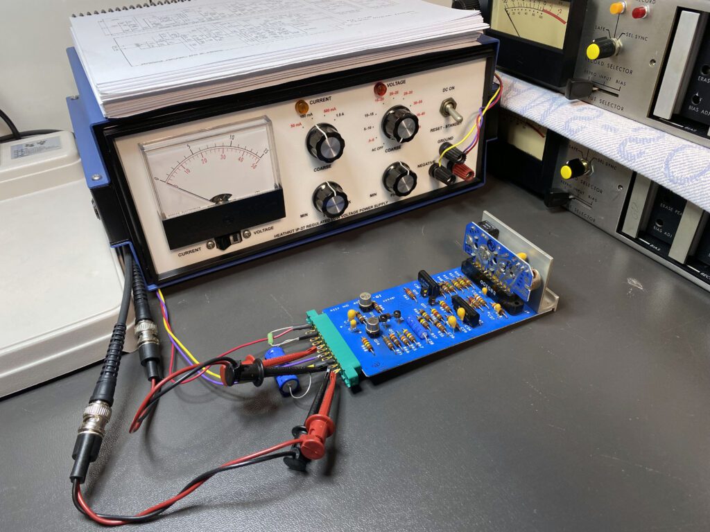
Of the three Record amplifiers available, two were installed for testing in the AG-440. The third Record amp smoked upon power-up, so that’s where bench work started. After purchasing a 12-pin PCB card edge connector (TRW 50-24A-30), a test fixture was built to check performance of the Record preamp. This setup is shown in the photo above.
Several issues were identified with the “smoke” board, and then with the other two Record PCBs. As purchased on eBay, none of the three functioned. The “smoke” unit had a bad tantalum capacitor. The other two PCBs had multiple transistor failures. Because of the design of the output stages of the Record amplifier, a failure in one transistor tended to cause other devices that were direct-coupled to fail. In all, four transistors (two drivers and two output) on each of two boards were replaced.
This task was complicated initially by the lack of a standard part number for the transistors. In the Ampex manual, an internal numbering system is used (e.g., 014-698). Fortunately, a web search turned up an extremely helpful cross reference. See the Ampex Transistor Cross Reference List. Armed with JEDC part numbers, substitute transistors were identified and installed. Problem solved.
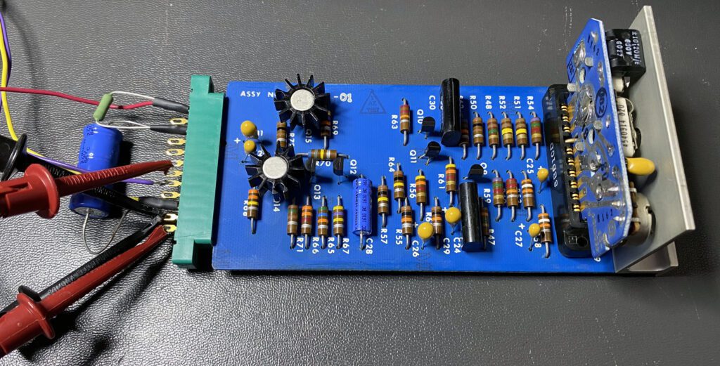
Curiously, the problem with two of the Record amplifiers (the ones that didn’t “smoke”) were the driver and output transistors. After replacement, it was noted that the transistors tended to run warm while operating. As a safety measure, a small press-on heatsink was added to each of the output devices. This may prevent future failures. A finished board is shown in the photo above.
In the course of troubleshooting the Record amplifier boards, detailed measurements were taken in order to fully characterize how a properly operating device should perform. Those measurements are available for download. (See the Available Downloads blog.) They may be helpful when troubleshooting the AG-440 Record amplifier PCB on the bench.
Measurements were next taken on the Reproduce amplifier boards in a bench test environment. Those measurements are also available for download.
Day 16 – Testing Completed
With the Record modules working properly, tests on the overall system were conducted, with good results.
Since the playback circuits had already been optimized (including tape head alignment), setup of the record system was based on performance through the playback system. The bias was adjusted per the Ampex instruction manual, followed by head alignment and adjustment of equalization. The overall (record to reproduce) results were good, although not quite to specifications. The working tape used for these tests is of uncertain history. Excessive oxide shedding has been observed. Due to the possibility of tape damage during tests on the transport, I was not particularly concerned about the ultimate performance of the reel. A NOS reel of tape will be used for final alignment after the machine is installed in its cabinet and moved into the 1970s radio studio.
With initial work completed on the AG-440, the focus shifts to the cabinet. Many options were entertained, from duplicating the Ampex cabinet to various custom implementations. While duplicating the Ampex cabinet was an attractive solution, the space requirements were considerable. That’s a concern because space is limited in the studio. Also, it would have been quite expensive. So, the decision was made to go with a stock Middle Atlantic rack cabinet. The benefits include lower cost, immediate availability, and much less required floor space.
Day 17 – Project Completed
Today marked completion of the restoration project. The machine was mounted in its cabinet and installed in the studio.
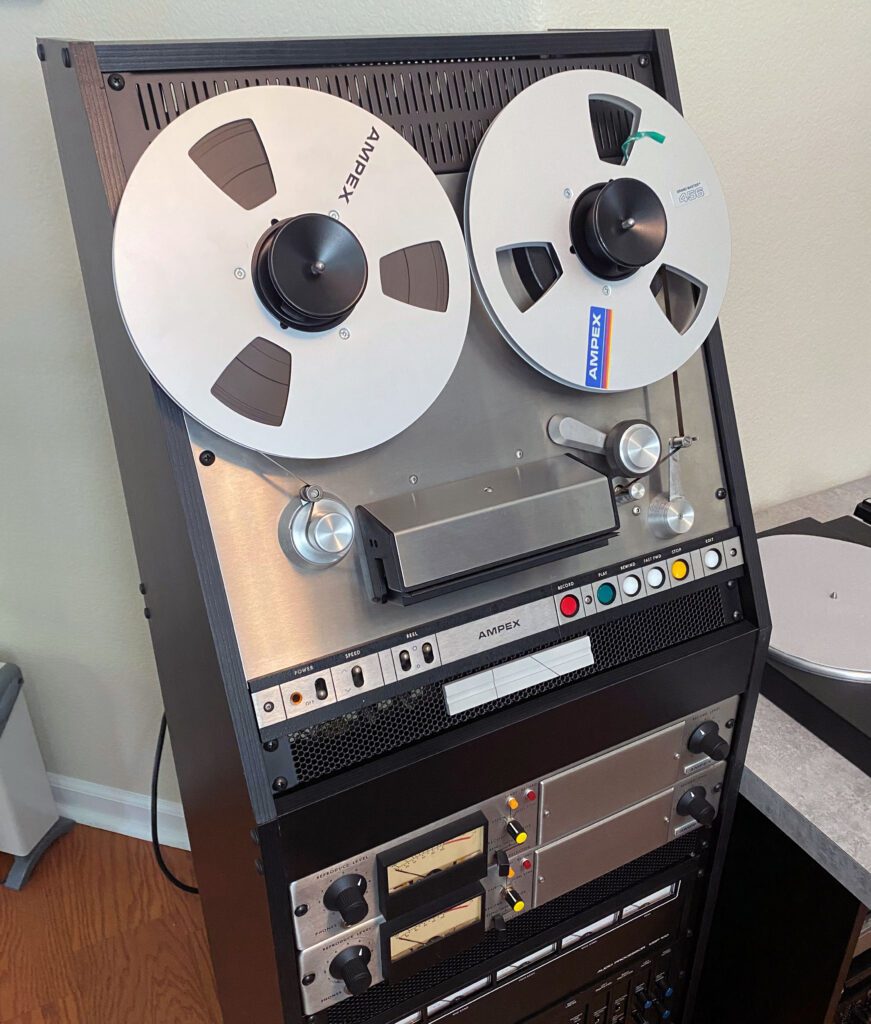
The Middle Atlantic rack worked out very well. It has an inclined top piece that is perfect for reel-to-reel machines. The preamplifiers are mounted below the transport. With the space-efficient inclined rack, the AG-440 fits nicely into the 70s studio. The cabinet is on casters to facilitate movement as required. An umbilical cable connects the rack to the Gates Executive console.
With completion of the project, an assessment can be made of the choices made along the way. I probably couldn’t have done better than the transport purchased on eBay. The preamplifers were another story, but the end result was good. The original 4x cost estimate described above was about correct, once all purchases are considered.
I have been tempted to add another AG-440 to the studio, but resisted the temptation because of the cost and time commitment required to restore this type of machine. For me, the most challenging part of a restoration project is cleaning up the hardware when it comes in the door. It’s usually messy and unpleasant work. Having said that, the end result turned out quite well.
Having finished with this project, time to move on to the next one.