Vacuum Tube Amplifier Projects
Over the years, I have built a number of vacuum tube amplifiers for family and friends. It’s been a fun hobby and a great excuse to buy more equipment for the workroom. Anyway, some of those projects are documented in the entries below. Downloads for the projects are available on the Downloads blog on this web site.
The amplifier projects share a common architecture. The major differences can be found in the power supply—notably the power transformer, type of rectifier tube, and type of filter (choke-input or capacitor-input). In addition, different amplifier output tube types are used along with different output transformers. The power output achieved by the amplifier is a determined by these variables.
One of the things I have learned while building these products is that, if you want to do it right, it usually takes a long time. Back when I was in college and building all kinds of electronics gadgets, I focused strictly on building and not documenting. Many decades later, I focus as much on documentation as on building. In fact, my experience has been that for each of the completed projects, far more than half of the time spent has been focused on documentation. By documentation I include developing the schematic, parts list, layouts, key construction/assembly items, setup/alignment procedures, and measured performance. All this takes time. As such, it has been necessary to choose my projects wisely. Unfortunately, time is never unlimited (and neither is money).
20 W Stereo Amplifier
The WhitakerAudio 20 W stereo amplifier is a high-quality device intended for modest power output requirements. The amplifier features quality components throughout. Specifications are as follows:
- 10 W rms per channel rated output into 8 ohm load (12.5 W rms peak)
- Noise 70 dB below rated output (unweighted)
- Frequency response ± 1 dB 10 Hz to 50 kHz at typical listening level (5 W)
- Harmonic distortion 0.75% or less at typical listening level
- Intermodulation distortion 1.5% or less at typical listening level
- Line input impedance 100 k ohms, 1 V rms nominal for full power output
- Conservatively rated components used throughout
- Soft-start power supply to extend component life
- Adjustable output tube bias for optimal performance
- Power requirements: 120 V ac, 60 Hz, 120 W nominal
- Physical dimensions: 19-in wide by 16-in deep by 7-in high (note that the depth specification does not include back panel cables)
- Weight approximately 40 lbs
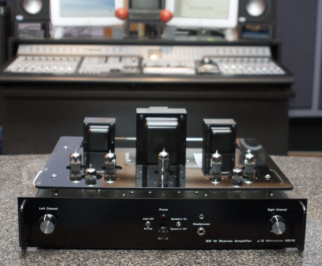
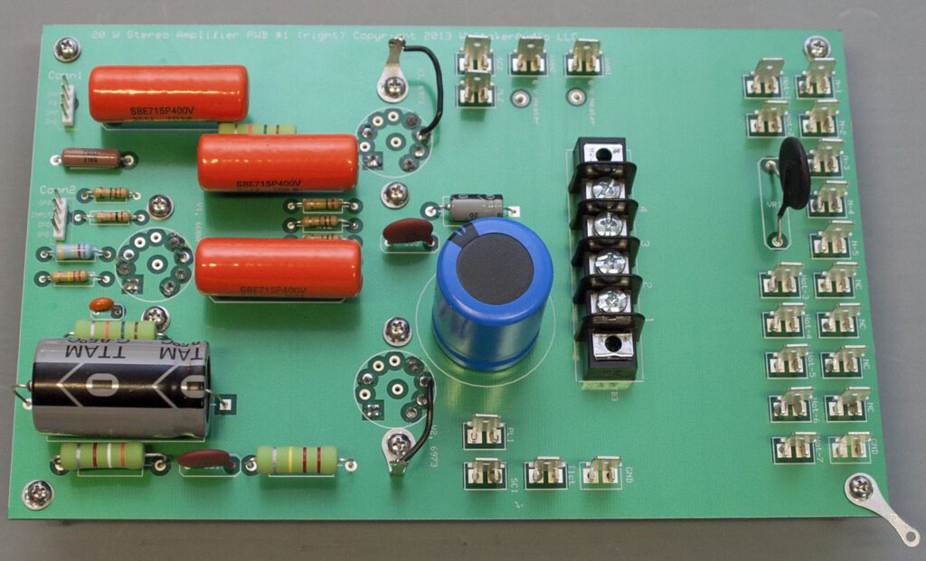
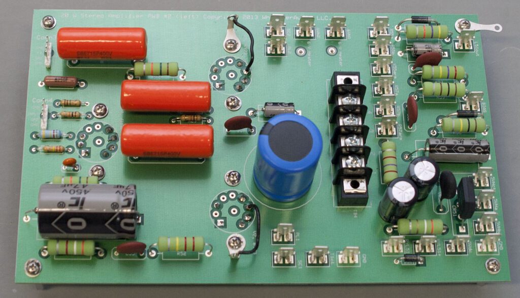
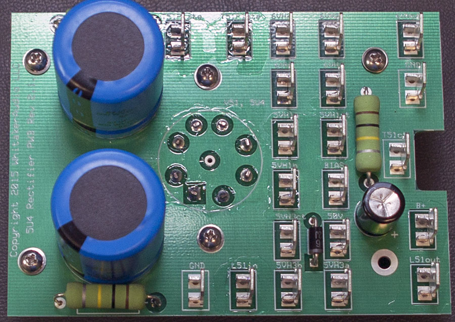
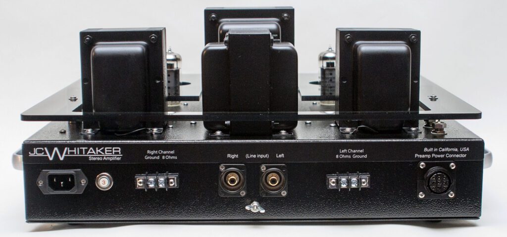
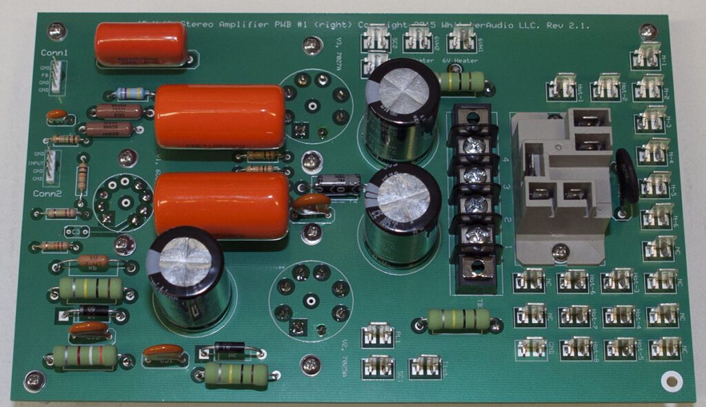
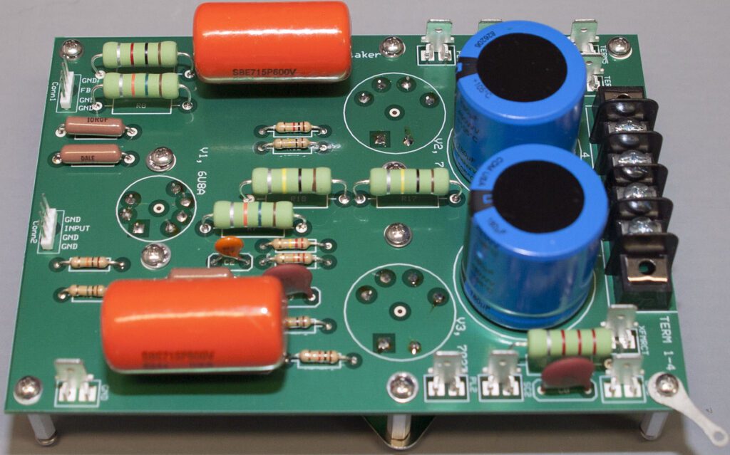
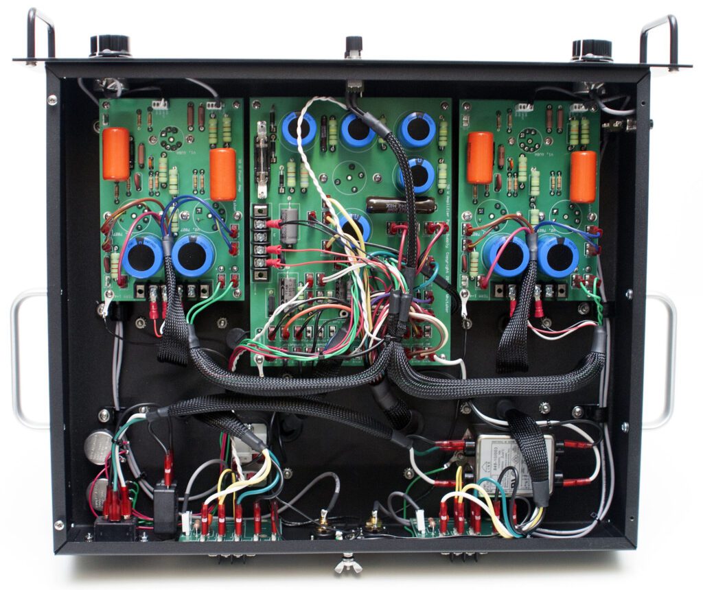
The amplifier is built around two main printed circuit boards (PCBs) and three special-purpose boards, engineered for top performance. Component placement and board traces have been engineered to minimize hum and noise. The boards feature a unique mounting technique for the vacuum tubes that keeps heat away from the PCB and minimizes hum in the amplifier. The PCBs are designed to reduce off-board connections, thereby simplifying layout and providing for controlled characteristics. The PCBs include top and bottom solder masks and top-side silk-screened legends.
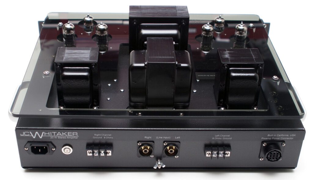
The power supply uses a vacuum tube rectifier feeding a choke and followed by a high-capacity bank of filter capacitors. The active circuits of the power amplifier utilize a 6U8A input amplifier and phase splitter. The power output stage is built around a matched pair of 6973 beam power tubes. Top-quality Hammond transformers are used throughout. The transformers are conservatively rated, providing wide operating margins.
The output circuit utilizes a screen-tap configuration to optimize sonic performance. Generous power supply filtering ensures ample reserve for the output stage.
Adjustable bias to the push-pull output tubes provides a wide range of operating points, allowing users to find a good middle point between top performance and long tube life.
Beyond the great specs, the amplifier sounds very nice. Clean. Warm. Interesting. Like a tube amp should sound.
The 20 W stereo amplifier is powerful enough to fill a room with great-sounding music, and small enough to be practical for headphone listening. Aside from the obvious application of this product in a home audio system, the 20 W stereo amplifier is ideal for use in computer sound applications—for driving speakers or headphone listening (or both).
Assembly details for the WhitakerAudio 20 W stereo amplifier, including circuit board layouts and detailed documentation, can be found on the Available Downloads blog on this site. In addition, see the Available Printed Documents blog.
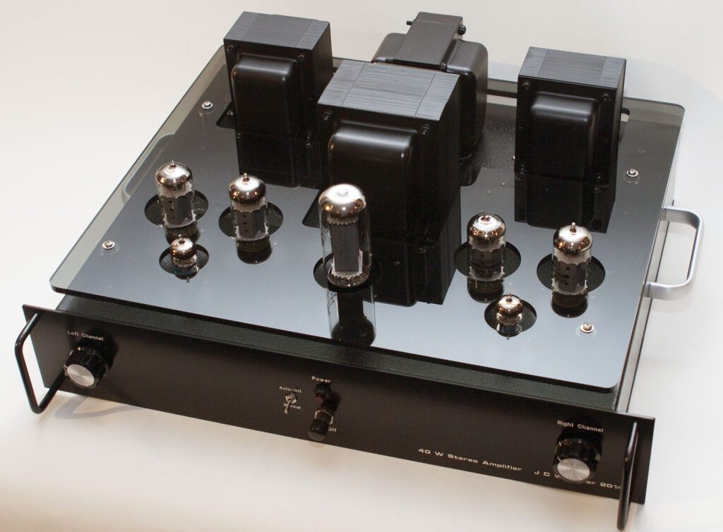
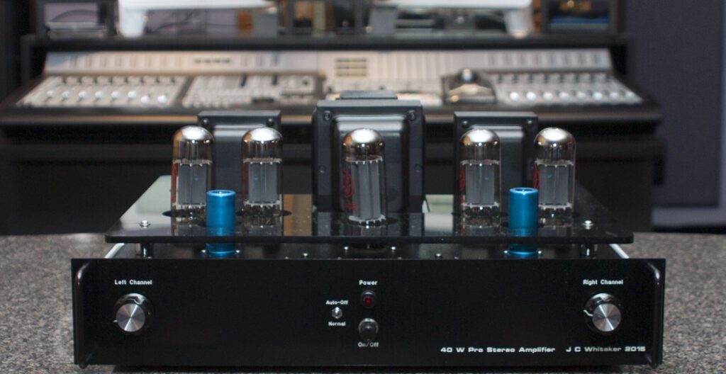
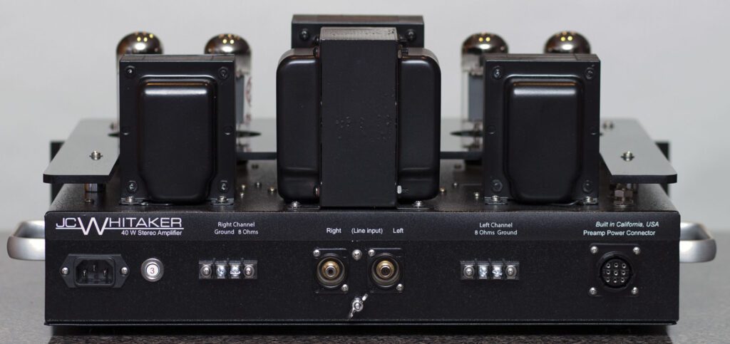
40 W Stereo Amplifier
The WhitakerAudio 40 W stereo amplifier is a high-quality device intended for moderate power output requirements. The product features quality components throughout. Overview specifications:
- Maximum of 20 W per channel rated output into 8 ohm load
- Sensitivity 1.0 V rms for full power output
- Input impedance 100 k ohms
- Noise 90 dB below rated output (unweighted)
- Frequency response ±1 dB 10 Hz to 100 kHz at typical listening level (5 W)
- Harmonic distortion 0.5% or less at typical listening level
- Intermodulation distortion 0.4% or less at typical listening level
- Conservatively rated components used throughout
- Soft-start power supply to extend component life
- Adjustable output tube bias for optimal performance
- Power requirements: 120 V ac, 60 Hz, 150 W nominal.
- Physical dimensions: 19-in wide by 16-in deep by 8-in high. Note that the depth specification does not include back panel cables.
- Weight approximately 47 lbs.
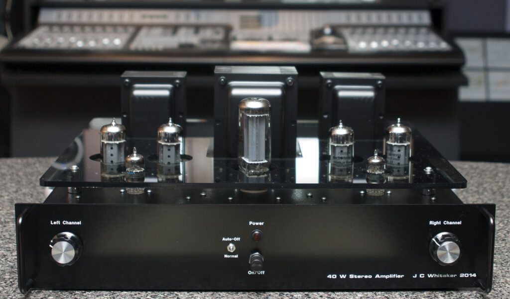
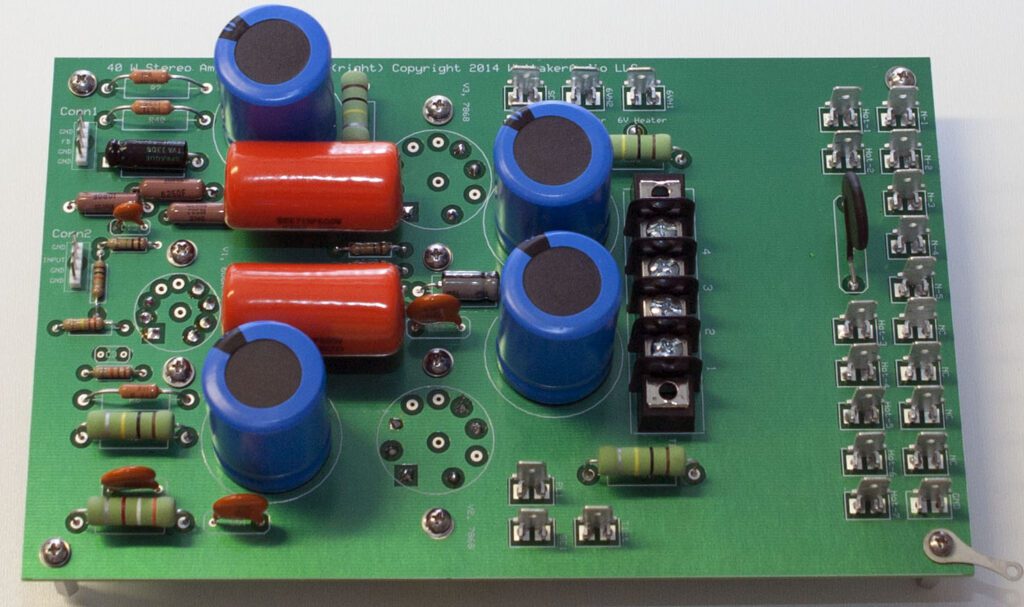
The amplifier is built around three main printed circuit boards (PCBs) and two special purpose boards, engineered for top performance. A ground plane covers the component side of the PCBs. Component placement and board traces have been engineered to minimize hum and noise. The boards feature a unique mounting technique for the three vacuum tubes used in each channel that keeps heat away from the PCB and minimizes hum in the amplifier.
The PCBs are engineered to reduce off-board connections, thereby simplifying layout and providing for controlled characteristics from one unit to the next. The PCBs include top and bottom solder masks and top-side silk-screened legends.
The output circuit utilizes a screen-tap configuration to optimize sonic performance. Generous power supply filtering ensures a rock-steady reserve for the output stage.
Adjustable bias to the push-pull output tubes provides a wide range of operating points, allowing users to find a good middle point between top performance and long tube life.
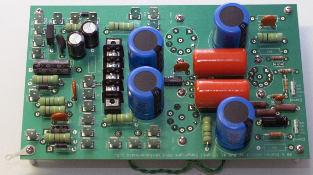
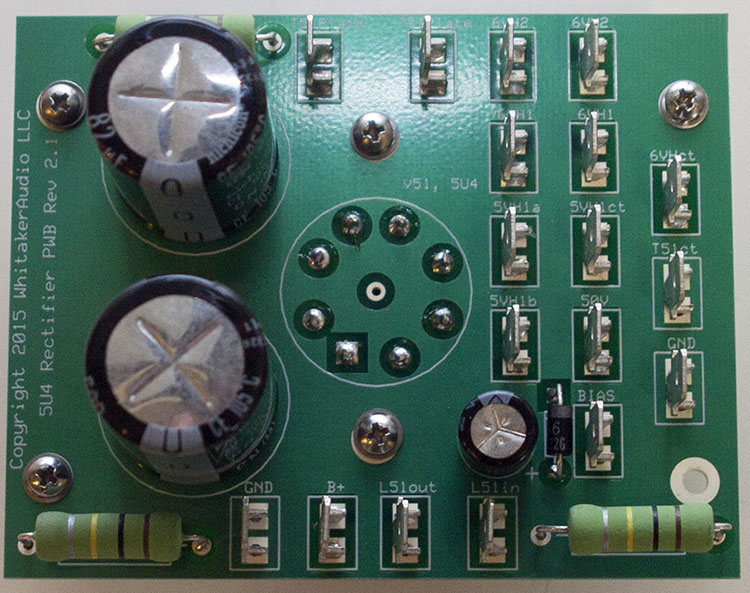
The power supply uses a 5U4 rectifier tube feeding a high-capacity bank of filter capacitors and choke. The active circuits utilize a 6U8A input amplifier and phase splitter. The power output stage is built around a matched pair of 7868 beam power tubes. Top-quality Hammond transformers are used throughout. The transformers are conservatively rated, providing wide operating margins.

Beyond the great specs, the amplifier sounds very nice. Clean. Warm. Interesting. Like a tube amp should sound.
Assembly details for the WhitakerAudio 40 W stereo amplifier, including circuit board layouts and detailed documentation, can be found on the Available Downloads blog on this site. In addition, see the Available Printed Documents blog.
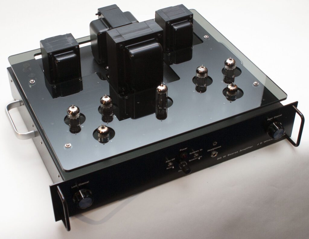
40 W XL Stereo Amplifier
The WhitakerAudio 40 W “XL” stereo audio amplifier is a high-quality device intended for high power output requirements. The “extra-large” (XL) 40 W amplifier is just that—over-sized for peak performance. The 40 W XL uses powerful 7027A beam power tubes, supported by a heavyweight power supply that has plenty of reserve energy. The amplifier features quality components throughout. Overview specifications are as follows:
- Rated output of 20 W per channel into an 8 ohm load
- Input impedance 100 k ohms
- Sensitivity 1.0 V rms for full power output
- Noise 85 dB below rated output (unweighted)
- Frequency response ±1 dB 10 Hz to 95 kHz at typical listening level (5 W)
- Harmonic distortion 0.4% or less at typical listening level
- Intermodulation distortion 0.4% or less at typical listening level
- Conservatively rated components used throughout
- Soft-start power supply to extend component life
- Adjustable output tube bias for optimal performance
- Power requirements: 120 V ac, 60 Hz, 240 W nominal.
- Physical dimensions: 19-in wide by 16-in deep by 8-in high. Note that the depth specification does not include back panel cables.
- Weight approximately 60 lbs.
The active circuits utilize a 6U8A input amplifier and phase splitter. The power output stage is built around a matched pair of 7027A beam power tubes. Top-quality Hammond transformers are used throughout. The transformers are conservatively rated, providing wide operating margins.
The output circuit utilizes a screen-tap configuration to optimize sonic performance. Generous power supply filtering ensures an ample reserve for the output stages.
The amplifier is built around two main printed circuit boards (PCBs) and three special purpose boards, engineered for top performance.
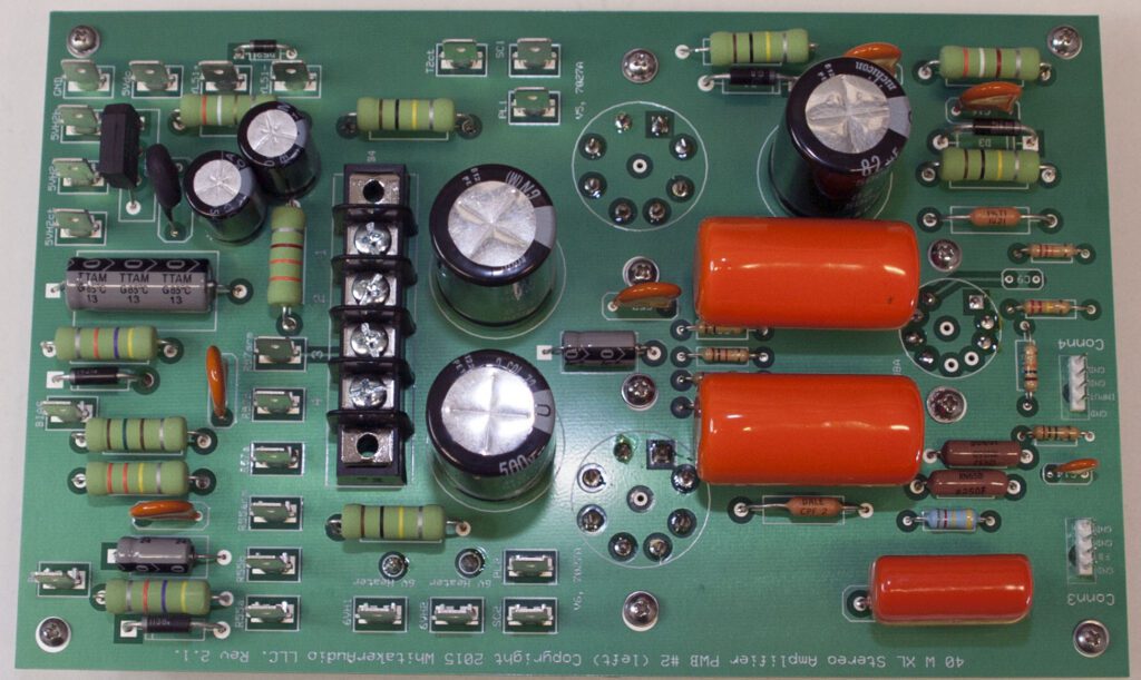
A ground plane covers the component side of the PCBs. Component placement and board traces have been engineered to minimize hum and noise. The boards feature a unique mounting technique for the three vacuum tubes used in each channel that keeps heat away from the PCB and minimizes hum in the amplifier. The PCBs include top and bottom solder masks and top-side silk-screened legends.
The PCBs are engineered to reduce off-board connections, thereby simplifying layout and providing for controlled characteristics.
Adjustable bias to the push-pull output tubes provides a wide range of operating points, allowing users to find a good middle ground between top performance and long tube life.
The power supply uses a heavy-duty Hammond plate transformer boasting 1 kV ac output. A 5U4 rectifier tube feeds an over-sized choke and high-capacity bank of filter capacitors. At full rated power for both channels, the power supply coasts at about 75% of capacity.
Beyond the great specs, the amplifier sounds very nice. Clean. Warm. Interesting. Like a tube amp should sound.
Assembly details for the WhitakerAudio 40 W XL Stereo Amplifier, including circuit board layouts and detailed documentation, can be found on the Available Downloads blog on this site. In addition, see the Available Printed Documents blog.
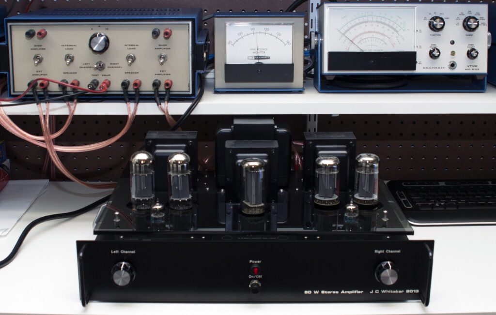
60 W Stereo Power Amplifier
The WhitakerAudio 60 W stereo power amplifier is intended for consumer applications requiring high power output from a vacuum-tube-based device. General specifications are as follows:
- Maximum of 30 W per channel peak output into 8 ohm load
- Sensitivity 0.92 V rms for full power output
- Noise 90 dB below rated output (unweighted)
- Frequency response ±1 dB 10 Hz to 30 kHz at typical listening level (5 W)
- Harmonic distortion 0.7% or less at typical listening level
- Intermodulation distortion 0.9% or less at typical listening level
- Conservatively rated components used throughout
- Soft-start power supply to extend component life
- Adjustable output tube bias for optimal performance
- Power input requirements: 120 V ac, 60 Hz, 170 W nominal.
- Physical dimensions: 19-in wide by 16-in deep by 8-in high (note that the depth specification does not include back panel cables)
- Weight approximately 47 lbs.
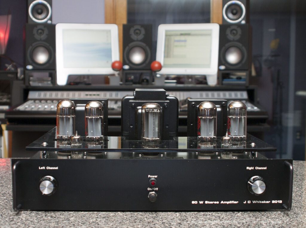
Beyond the great specs, the amplifier sounds very nice. Clean. Warm. Interesting. Like a tube amp should sound.
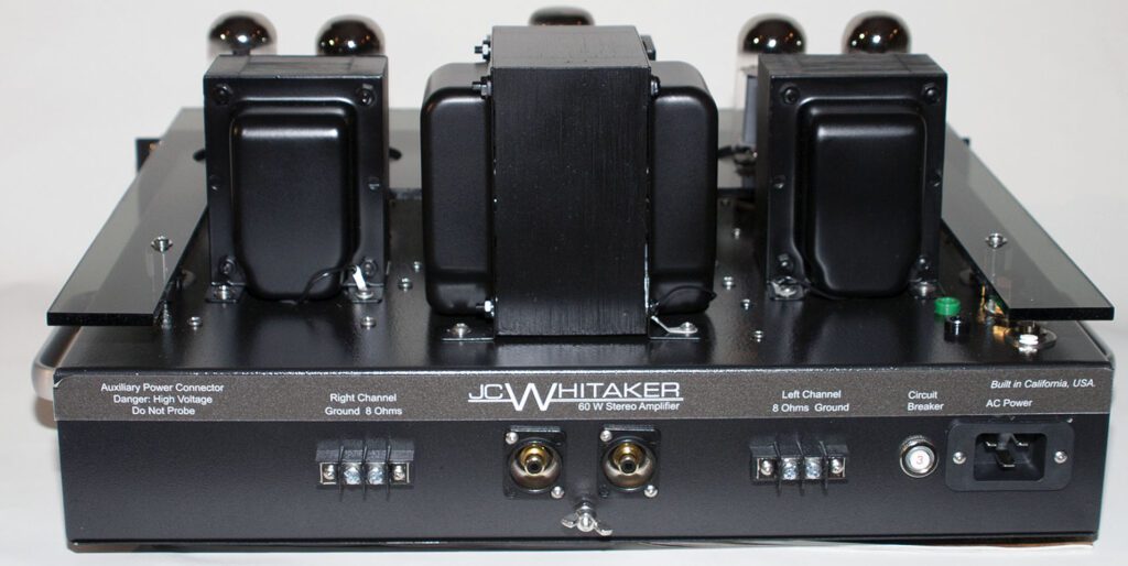
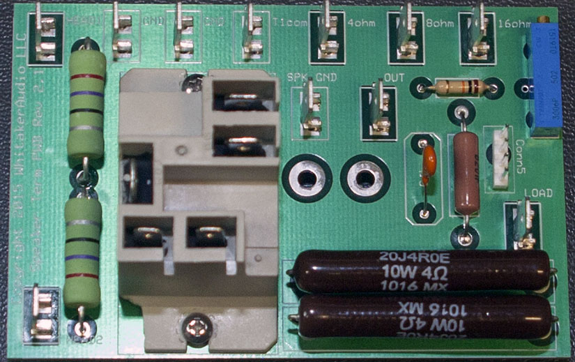
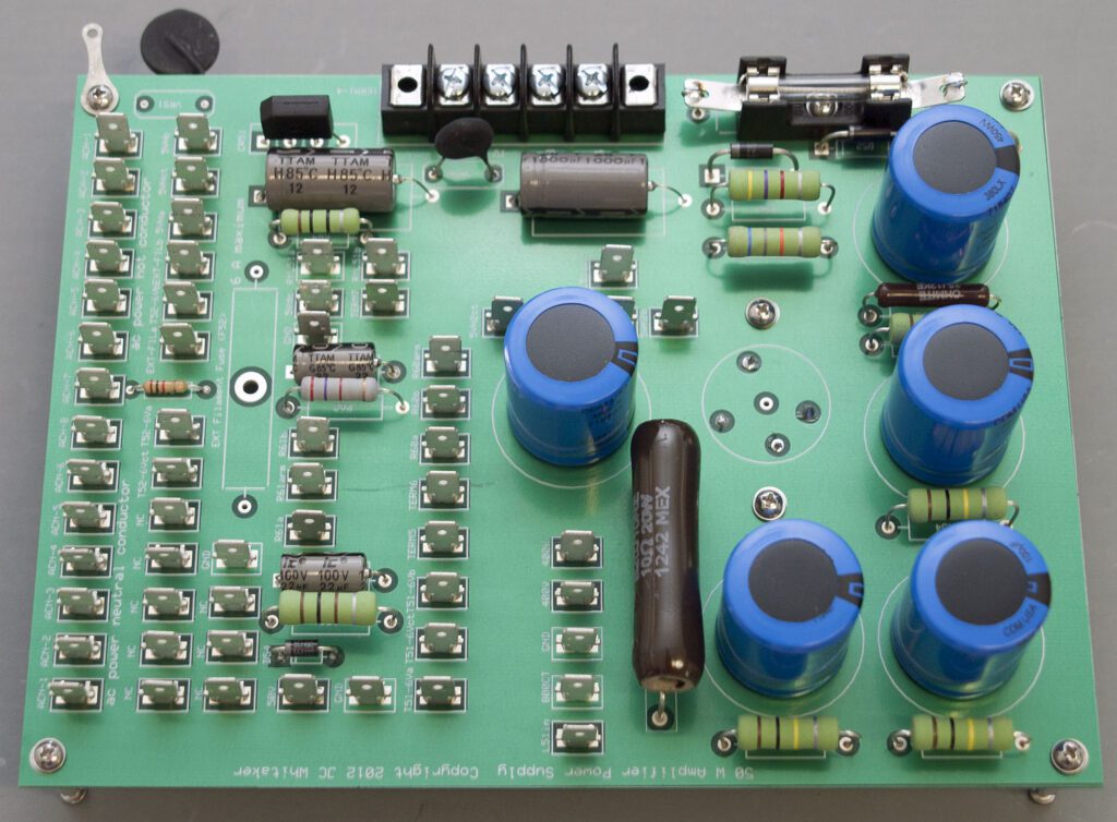
The amplifier is built around three main printed circuit boards (PCBs) and two smaller PCBs. The boards are engineered for top performance. A ground plane covers the component side of the PCB. Component placement and board traces have been engineered to minimize hum and noise. The boards feature a unique mounting technique for the three vacuum tubes used in each channel that keeps heat away from the PCB and minimizes hum in the amplifier.
The PCBs are engineered to reduce off-board connections, thereby simplifying layout and providing for controlled characteristics. The power supply uses a 5U4 rectifier tube feeding a choke and high-capacity bank of filter capacitors. The PCBs include top and bottom solder masks and top-side silk-screened legends.
The active circuits utilize a 6U8A input amplifier and phase splitter. The power output stage is built around a matched pair of 7027A beam power tubes. Top-quality Hammond transformers are used exclusively. The transformers are conservatively rated, providing wide operating margins.
The output circuit utilizes a screen-tap configuration to optimize sonic performance. Generous power supply filtering ensures ample reserve for the output stage.
Adjustable bias on the push-pull output tubes provides a wide range of operating points, allowing the user to find a good middle ground between top performance and long tube life.
Assembly details for the WhitakerAudio 60 W stereo power amplifier, including circuit board layouts and detailed documentation, can be found on the Available Downloads blog on this site. In addition, see the Available Printed Documents blog.
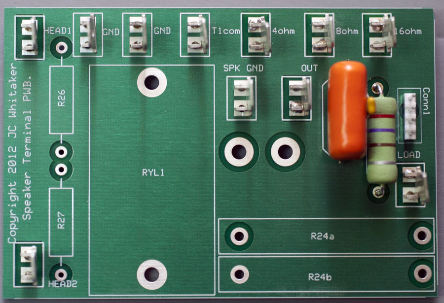
Add-on Enhancement Boards for the 20/40/60 W Stereo Amplifiers
The chassis for the amplifiers described above can accommodate optional add-on circuit boards that provide additional functionality. The add-on functions include:
- Power supply for separate vacuum tube preamplifier
- Automatic circuit protection, including auto-off feature
- Enhanced power management features
- Transistorized phono preamplifier and tone control
The design of the amplifiers and companion add-on PCBs allow the builder to install new features as desired. The PCBs are described below.
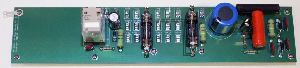
Preamp Power Supply PCB
When assembling a built-it-yourself audio system, it is convenient to use the power amplifier as a source for B+ and filament voltages for a companion vacuum tube-based preamplifier. The Preamp Power Supply board shown below fulfills this function. The board utilizes the high-voltage and filament supplies from the amplifier and adds the necessary switching and conditioning functions.
Power is delivered to the companion preamplifier via a 9-pin connector on the back panel of the amplifier. The PCB mounts on one side of the amplifier chassis.
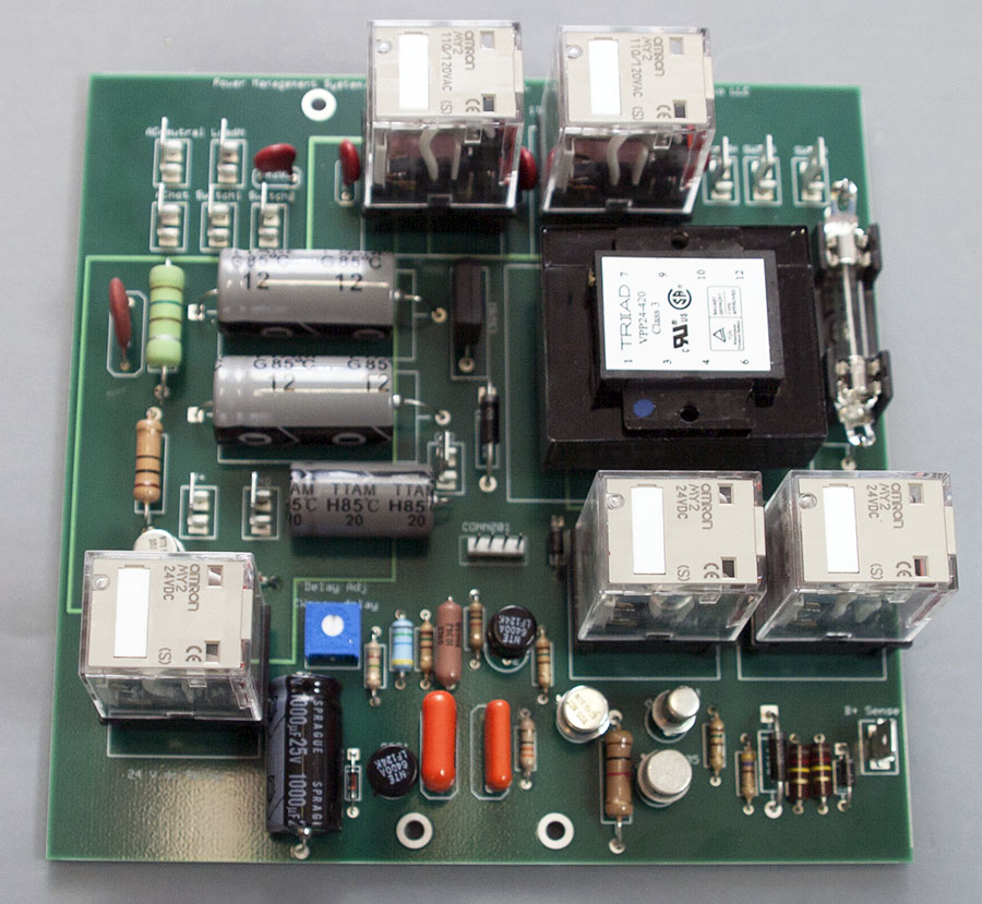
Power Management PCB
The power management circuit board is a supervisory device that adds additional layers of protection to the built-in protection already provided on the amplifier. The power management system adds the following features:
- Automatic shutoff. While is possible to operate the amplifier continuously for long periods of time, most consumers would likely prefer to not do so. Experience has shown the amplifier may be tuned on to play one or more records and then inadvertently left on after the record ends. Automatic Shutoff provides a fixed maximum run time for the amplifier—adjustable to about one hour, +/– 15 minutes. This time delay can be defeated at the option of the consumer.
- Over temperature Shutdown. The amplifier is designed to operate reliably at normal room temperature. If operated at an elevated temperature, component damage or shortened tube life could result. This feature shuts down the amplifier if the temperature inside the chassis exceeds 170°F. This is well below the maximum rated operating temperature of the amplifier components.
- Under-voltage shutdown. The power supply is designed to operate reliably under a wide range of conditions. It is possible, however, that because of the failure of a tube or another component, the power supply could be loaded to the point that continued operation could result in damage to one or more devices. This circuit monitors the plate voltage supply at power-up and shuts down the amplifier if the B+ voltage is below normal.
These functions are implemented on the Power Management PCB, shown below.
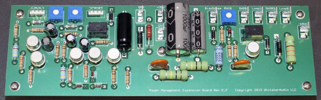
Power Management Expansion PCB
The power management expansion board adds additional functionality to the power management system, specifically:
- The auto-off feature is modified to switch the amplifier off about one hour after no output is detected at the speaker terminals. With the basic power management system, the auto-off feature is initiated after a fixed time period, not based on whether audio is being reproduced by the speakers. The expansion board changes that.
- The bias voltage is monitored to make certain it does not drop below –20 V dc. If the bias voltage is too low, it can result in shortened tube life; in extreme cases, it can cause component damage. The expansion board monitors the bias voltage and removes power from the amplifier if the voltage is outside recommended operating limits.
- A chassis interlock is provided that will shut the amplifier down if the bottom plate is removed. This feature can be defeated for servicing.
The Power Management Expansion PCB is shown below. When used, it mounts on one side of the amplifier chassis.
Preamplifier/Tone Control PCB
Having a phono preamplifier and tone control system within the chassis of the power amplifier provides for a compact and convenient way to enjoy listening to vinyl records. Due to space limitations within the chassis, it may not be practical to implement these functions in a tube-based system. Therefore, a preamplifier/tone control PCB was designed using discrete transistors as the active devices. The design is from the “tube era” and so it fits well with vacuum tube-based products.
The add-on board, shown below, mounts on one side of the amplifier chassis.
Any of the optional boards described here can be added to the 20/40/60 W stereo amplifiers described above. The only restriction is that the Preamplifier Power Supply PCB and Preamplifier/Tone-Control PCB cannot be installed in the same chassis. That’s not an issue, of course, since there would be no need to use both.
Assembly details for the WhitakerAudio add-on optional boards, including circuit board layouts and detailed documentation, can be found on the Available Downloads blog on this site. In addition, see the Available Printed Documents blog.
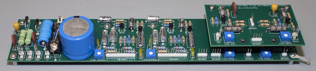
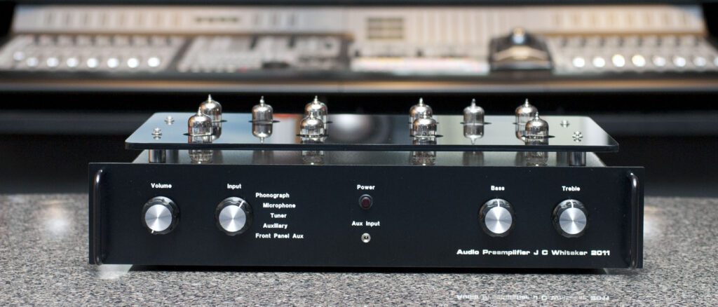
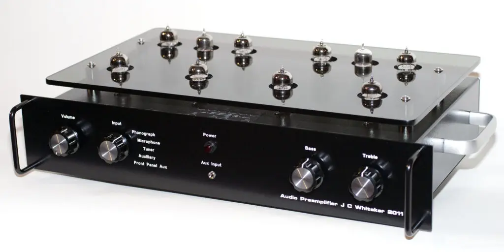
Stereo Preamplifier
The WhitakerAudio stereo preamplifier is a high-quality device intended for discriminating listening. The product features quality components throughout. This classic vacuum tube-based preamplifier provides five available inputs:
- Phonograph
- Microphone (high impedance)
- Tuner (100 k ohms input impedance)
- Auxiliary (100 k ohms input impedance)
- Front panel auxiliary (100 k ohms input impedance)
An input switch selects the desired source, which is fed to a tone-control stage and finally to an output buffer amplifier. An isolated “Tape Out” connector is provided for side-chain applications, such as recording on audio tape or on a computer. The Tape Out port is connected prior to the tone control stage.
The “Front Aux” input position connects to a front-panel jack for connection of a personal music device to the preamp.
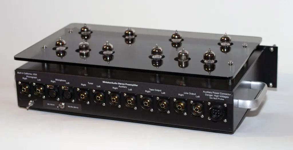
No power supply is included in the design, as the assumption is that this unit will be paired with a separate power amplifier, such as the WhitakerAudio 20 W stereo amplifier or WhitakerAudio 40 W stereo amplifier. A multi-pin connector ties the power supply of the amplifier to the preamp chassis. This has the benefit of reducing cost and at the same time reducing noise from the supply that could be picked up by the low-level preamp circuits.
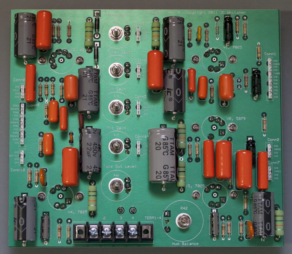
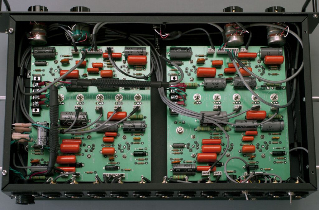
The stereo preamplifier is built around two printed circuit boards (PCBs), engineered for top performance. A ground plane covers the component side of the PCB. Component placement and board traces have been engineered to minimize hum and noise. The boards feature a unique mounting technique for the five vacuum tubes used in each channel that keeps heat away from the PCB and minimizes hum in the amplifier. The PCBs are engineered to reduce off-board connections, thereby simplifying layout and providing for controlled characteristics from one unit to the next.
The phonograph circuit uses a 7025 (12AX7) tube as the active stage. The microphone circuit uses a 5879 tube. The tone control stage is built around a 6EU7. The output buffer amplifiers are 7025 tubes.
Physical dimensions are 19-in wide by 12-in deep by 6-in high. Note that the depth specification does not include back panel cables. Weight is approximately 16 lbs.
This product has been designed and built for discriminating consumers, using classic technologies and new components. Beyond the great specs, the preamplifier sounds very nice. Clean. Warm. Interesting. Like a tube amp should sound.
The preamplifier generates little heat and (for a tube amplifier) consumes little power. Turn it on and let it run. Put on some music and enjoy audio as it should be heard.
Assembly details for the WhitakerAudio Stereo Preamplifier, including circuit board layouts and detailed documentation, can be found on the Available Downloads blog on this site. In addition, see the Available Printed Documents blog.
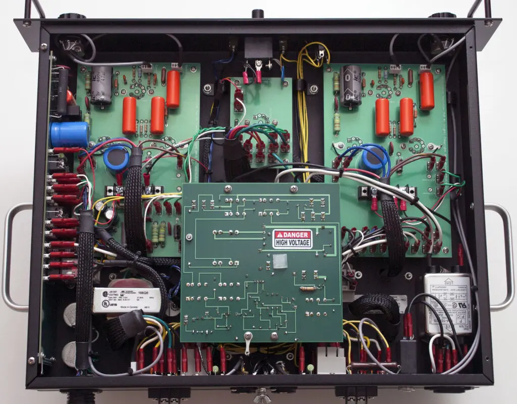
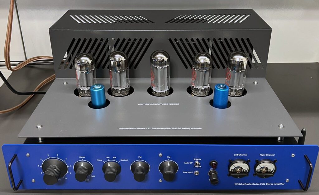
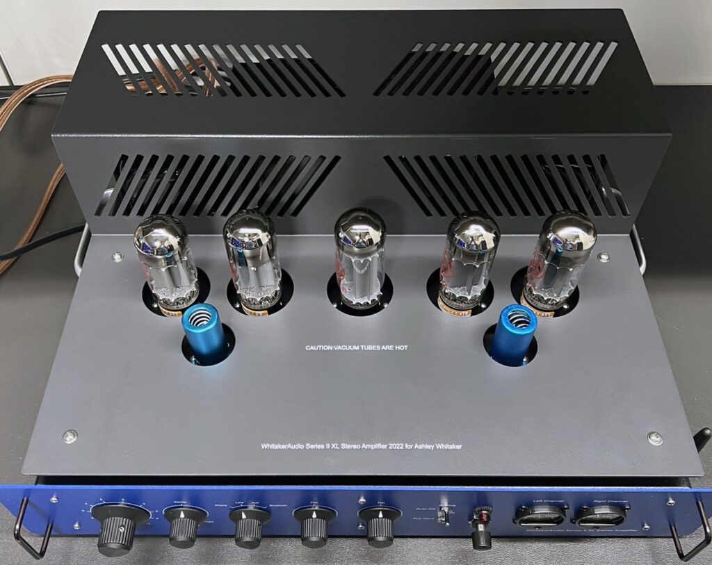
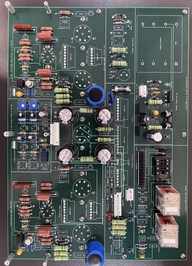
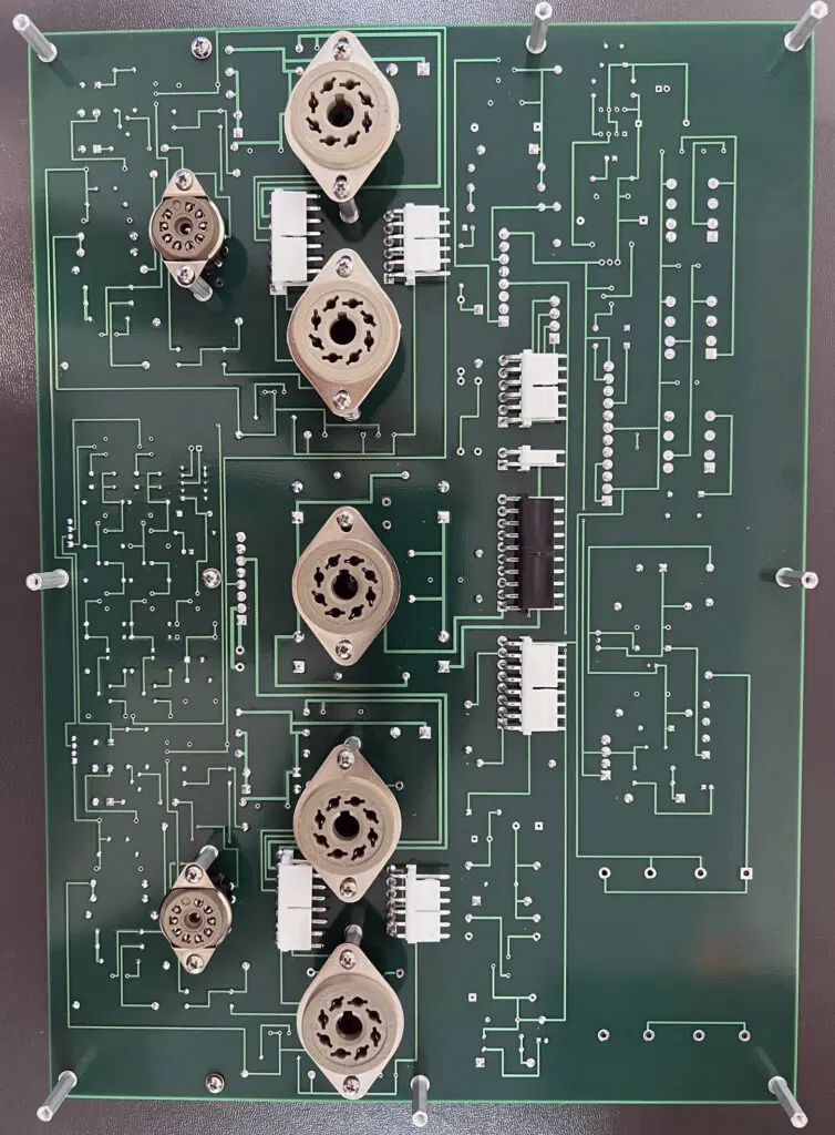
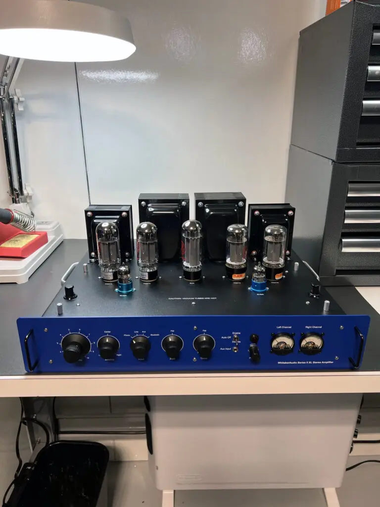
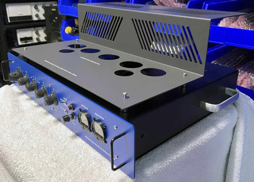
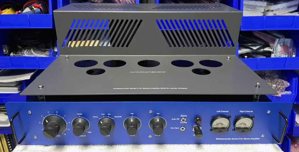
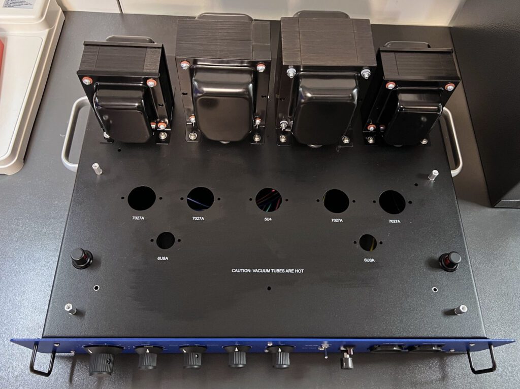
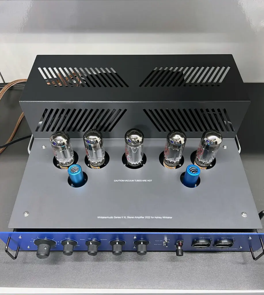
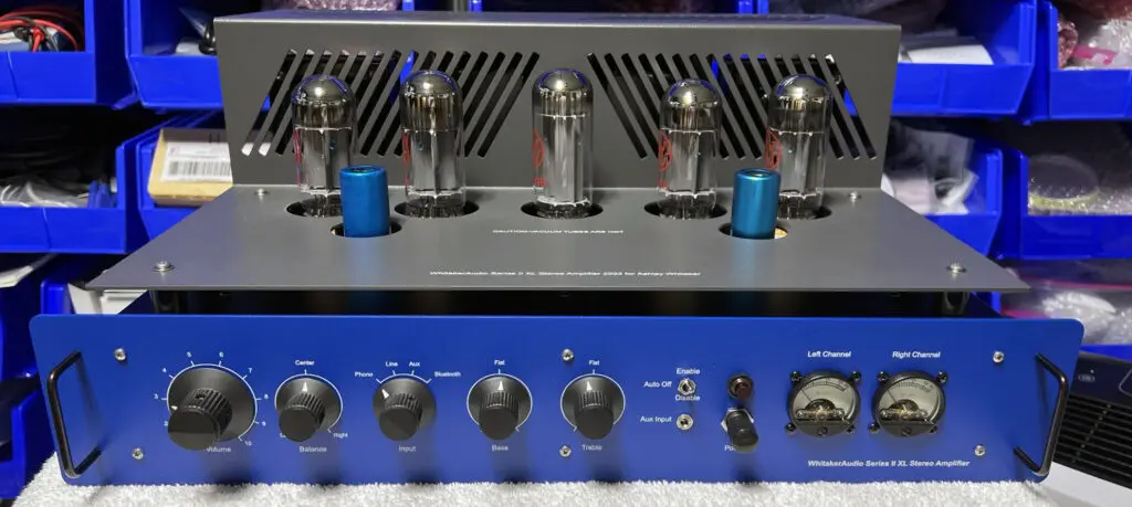
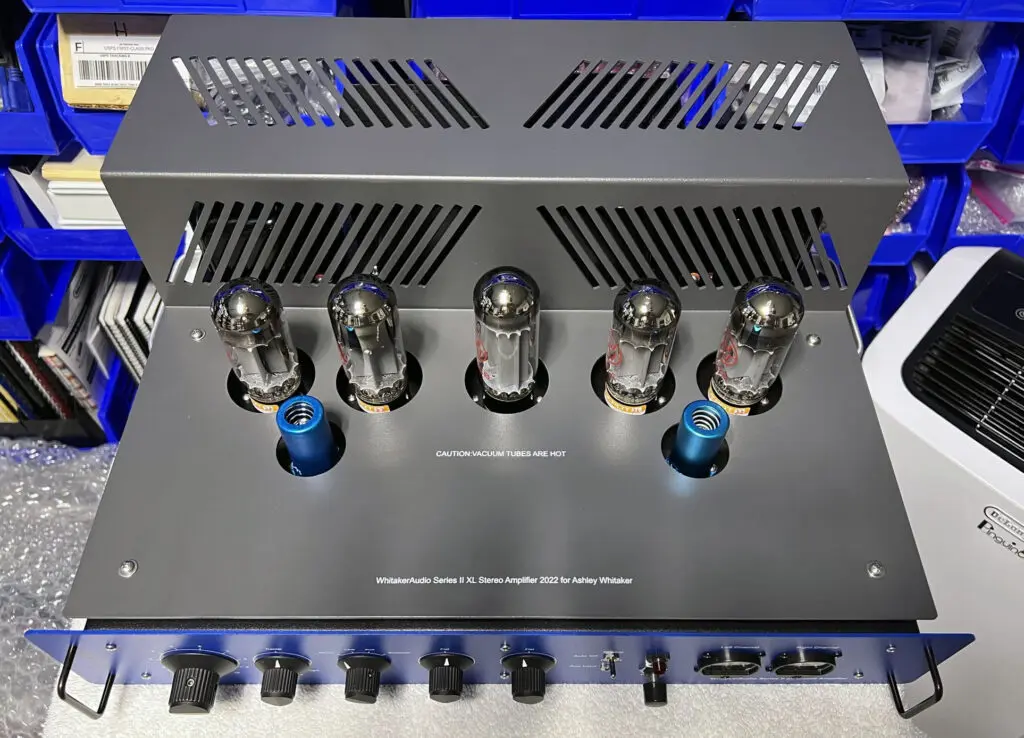
Latest Project: The Series II XL Integrated Stereo Amplifier
The latest vacuum tube based project is the WhitakerAudio Series II XL Integrated Stereo Amplifier. The “Series II” amplifier is a next-generation version of the 20/40/60 W amplifiers described above. The “extra-large” (XL) amplifier is just that—over-sized for peak performance. The amplifier is loaded with features—essentially everything that we could fit in the chassis. Overall specifications and features include:
- Tube-based amplifier providing medium power output levels; rated output of 20 W per channel into an 8 ohm load
- Low-noise phonograph preamplifier included
- Bluetooth receiver included
- Front panel switchable inputs (Phono, Line Input, Front Panel Aux, Bluetooth)
- Front Aux input impedance 10 k, 0.5 V rms nominal for full power output
- Line input impedance 10 k, 1 V rms nominal for full power output
- Front panel Bass and Treble tone controls to suit individual preferences
- Front panel Balance control for optimal stereo image
- Noise 80 dB below rated output (unweighted, line input)
- Frequency response ±1 dB, 20 Hz to 20 kHz
- Harmonic distortion less than 1% at full power output
- Intermodulation distortion less than 1% at full power output
- Soft-start power supply to extend component life
- Adjustable output tube bias for optimal performance
- Built-in system protection and auto-off feature included
- Power requirements: 120 V ac, 60 Hz, 240 W nominal
- Physical dimensions: 19-in wide by 15-in deep by 8-in high. Note that the depth specification does not include back panel cables
- Weight approximately 60 lbs
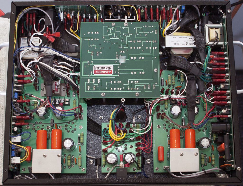
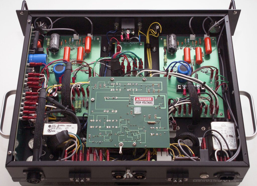
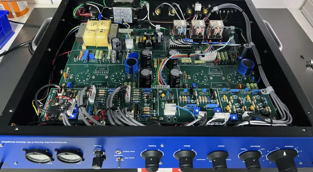
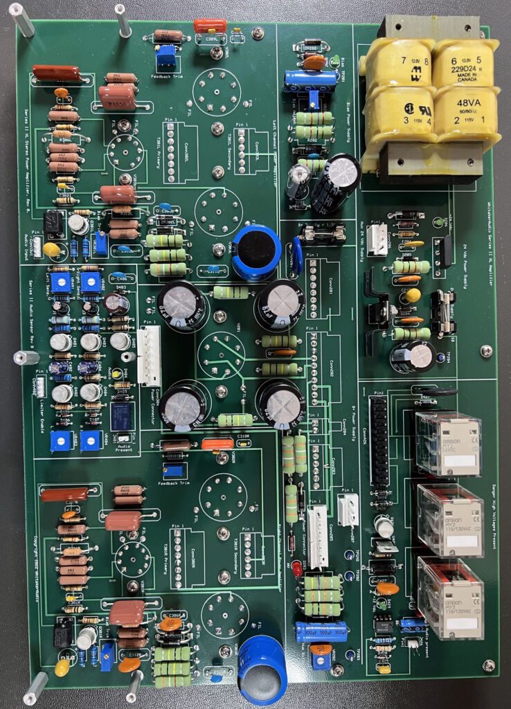
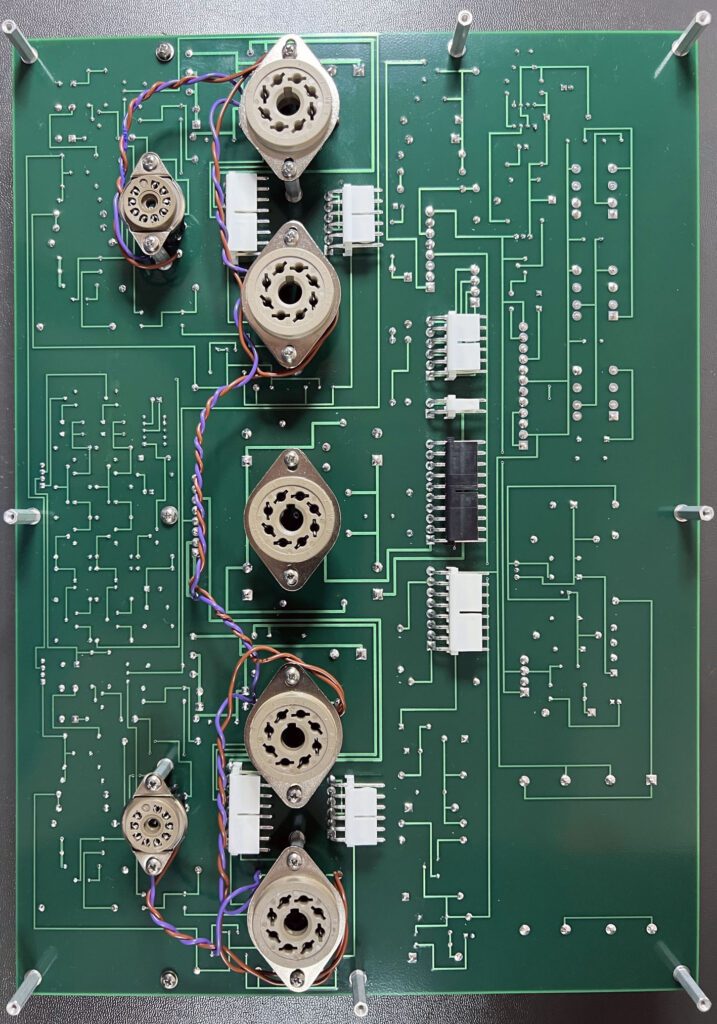
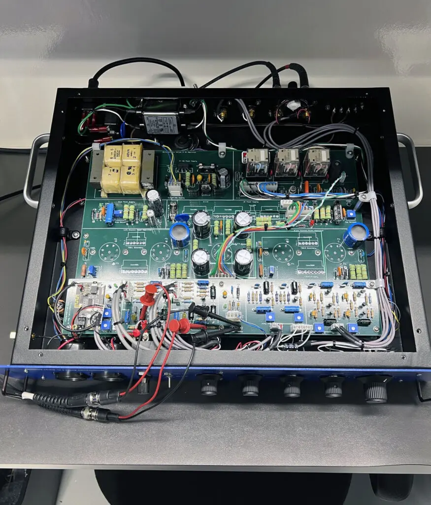
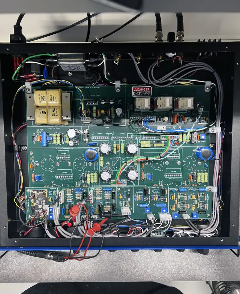
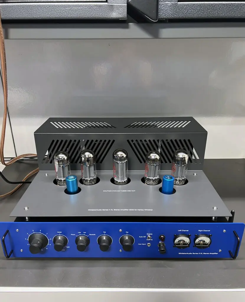
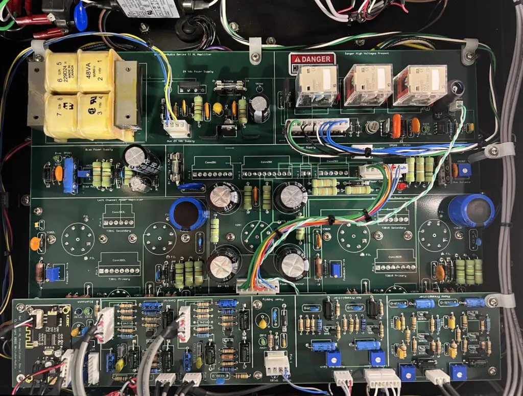
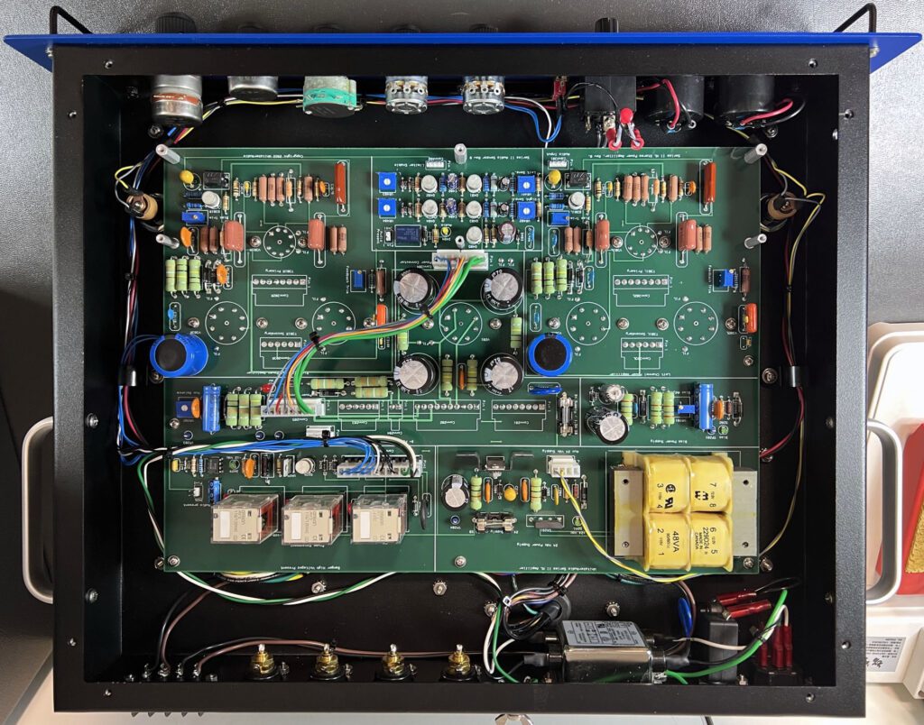
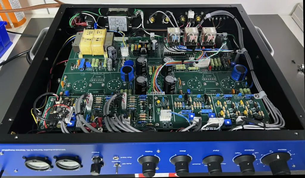
The amplifier is built around a single large 6-layer printed circuit board (PCB). Component placement and board traces have been engineered to minimize hum and noise. The board features a unique mounting technique for the vacuum tubes used in the amplifier that keeps heat away from the PCB and minimizes hum. The PCB includes top and bottom solder masks, and top-side silk-screened legends. The PCB is designed to reduce off-board connections, thereby simplifying layout and providing for controlled characteristics. The preamplifier PCB mounts on top of the main circuit board.
The phonograph preamplifier and tone control circuits utilize discrete transistors. The circuits are based on classic 1960s designs. This approach is intended to maintain the tube-era sound, even for a solid-state implementation. The benefits of transistors in this design include low noise and small physical size.
The power amplifier active circuits utilize a 6U8A input amplifier and phase splitter. The output stage is built around a matched pair of 7027A beam power tubes. Top-quality Hammond transformers are used throughout. The transformers are conservatively rated, providing wide operating margins.

The output circuit utilizes a screen-tap configuration to optimize sonic performance. Generous power supply filtering ensures ample reserve for the output stages.
Adjustable bias to the push-pull output tubes offers a wide range of operating points, allowing the user to find a good middle ground between top performance and long tube life. Optional front panel plate current meters provide a visual indication of the operating status of each channel.
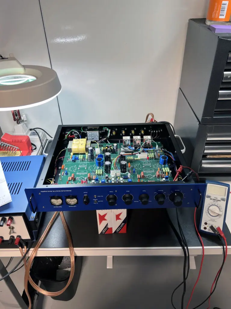
A gallery of photos showing assembly at various points in the process is given below.
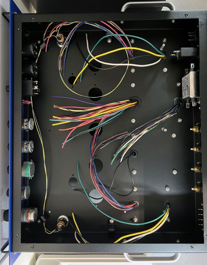
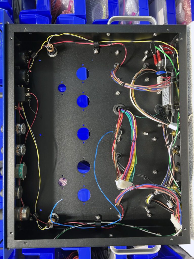
A detailed Assembly/User Manual was developed to guide the assembly process. It is often possible to identify flaws or errors in a design if the builder describes in detail how the circuit works and how it should be assembled before any parts are ordered. This was the case for the Series II XL Amplifier.
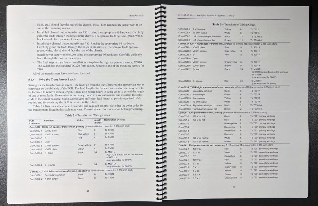
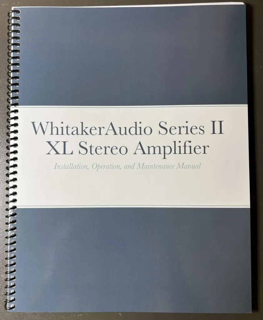
The Assembly/User Manual is available from the Available Downloads page on this web site. A printed version is available for purchase from the Available Printed Documents page.
The cost of building any project is an important consideration for the audio enthusiast and hobbyist. For the projects documented in this blog, the major cost centers are usually the circuit boards, transformers, and chassis. Builders could eliminate the PCB cost by using hand-wired terminal strip construction.
As with any electronic product, unit costs fall rapidly as the volume (number of units produced) increases. For a one-off project, however, there are are not many ways to reduce the cost without reducing the feature set.
Most of the projects documented in this blog were done in the 2012 to 2015 timeframe. At the time, the only way to build a vacuum tube amplifier was to settle on a design, acquire the parts, prepare the chassis, assemble the unit, and test the final product.
More recently, a revival of interest in vacuum tube amplifiers—driven in some part by a revival of interest in vinyl records—has resulted in companies building new vacuum tube amplifiers for consumers, both in assembled and kit versions. The kits can be found for sale in any number of places—Amazon and eBay, to name just two. These kits appear to be of high quality, and generally speaking are inexpensive compared to the build-it-from-scratch option. The good news is that audio enthusiasts have many options now with regard to building a vacuum tube amplifier. People who want to build it from scratch can still do that, of course. Given the choice, I’ll still build it from scratch.