70s Radio Studio Proof of Performance
One of the more significant duties of the Chief Operator at a radio station in the era of the Executive audio console was the annual Proof of Performance. This series of tests, mandated by the FCC, was a yearly ritual that engineers undertook to demonstrate that their station was operating within the minimum technical guidelines set forth by the Commission. Today, with all-digital equipment, the “Proof”(as it came to be known) is a minor task that stations can easily pass. Back in the day, however, meeting the minimum requirements, especially for an FM stereo station, was not a trivial matter. With analog equipment from the microphone input terminals to the stereo demodulator, each step in the chain offered the opportunity for problems. As such, the annual Proof was both a measurement task and a maintenance imperative.
The procedures for conducting the Proof were specified in the FCC Rules. As a help to station engineers, Broadcast Engineering magazine, a leading trade journal back in the day, published a “Proof of Performance Manual” that was widely used. I used it at the FM station I worked at in the late 1970s and early 80s. Some years later I would become Editor of the magazine, which was an awesome job…but that’s another story.
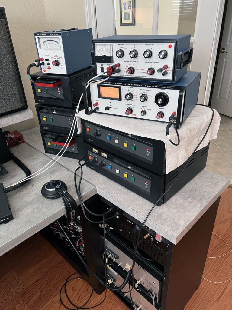
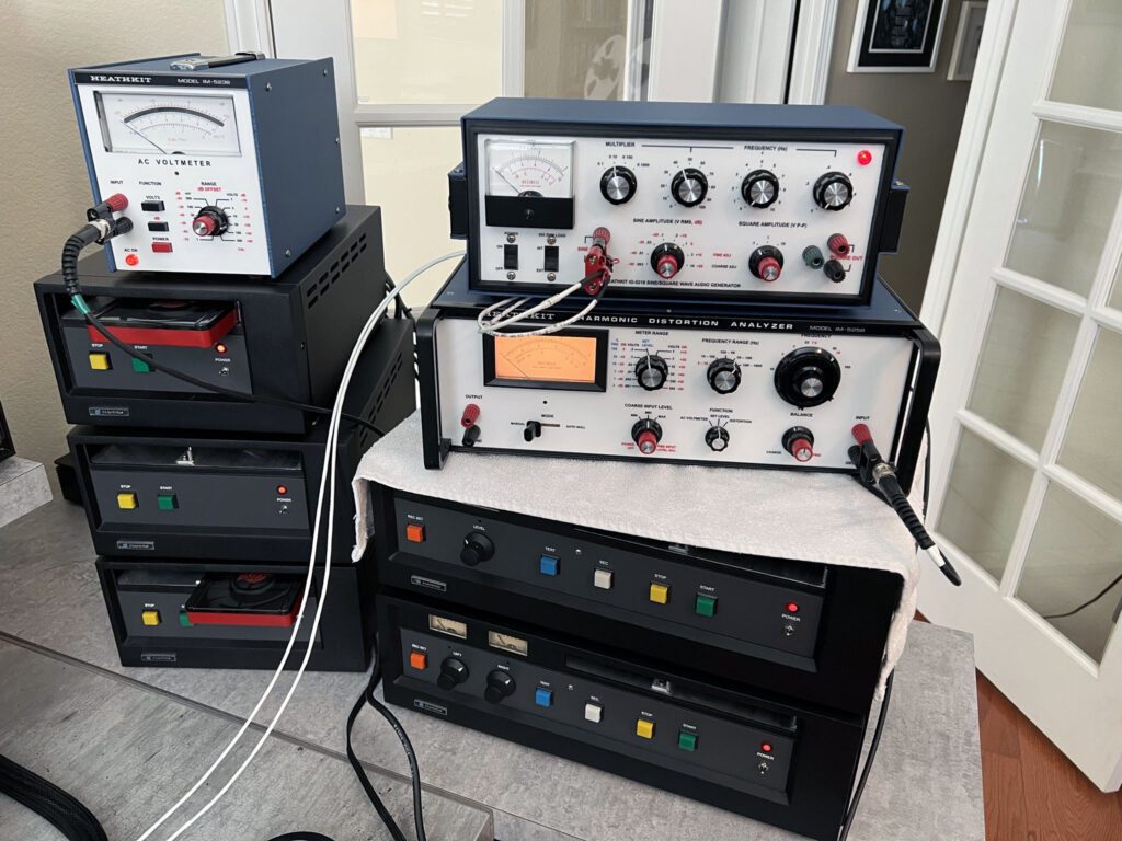
With the 1970s radio studio constructed and operating properly, a Proof was run on the system from the microphone input terminals to the off-air stereo demodulator. The test instruments used to conduct the measurements were the same type I used back in the 70s and 80s—a Heathkit IG 5218 audio signal generator, Heathkit IM 5258 harmonic distortion analyzer, and Heathkit IM 5238 audio voltmeter.

The test setup is shown above during measurements. The procedure is rather detailed, involving a number of readings taken at different operating points. With the proper equipment and assuming no surprises along the way, the measurements take several hours to complete.
The basic measurement set includes frequency response, harmonic distortion, noise, channel separation, and crosstalk. After the measurements have been recorded, frequency response and distortion are usually plotted on appropriate graphs. Since the measurements are made at discrete frequencies, a French curve is used to create the final traces from discrete values, per the usual practice of the time. Definitely Old School.

The intent of the Proof is to determine the performance of the entire program and transmission chain. The path is as follows: microphone input terminals of the Executive console / patch bay / distribution amplifier / twisted pair wiring (Cat5) to the Collins 310Z-2 exciter and 786V-1 stereo generator / signal radiated at low power / TFT 765A preselector and 763 FM modulation monitor / TFT 724 stereo monitor.
The results of the Proof were encouraging. All parameters were within the FCC limits, except for noise and stereo separation at certain frequencies. In both cases the measurements were within a couple dB of the targets. So, for 40 to 50 year old equipment, very good results.