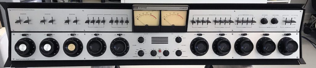
Gates Executive Audio Console Restoration, Part 2: Power On
The blog picks up where the first one left off. The console has been cleaned and reassembled. The following posts document the steps taken to get the console back in the studio and on the air.
Day 15 – Power On
Power on!
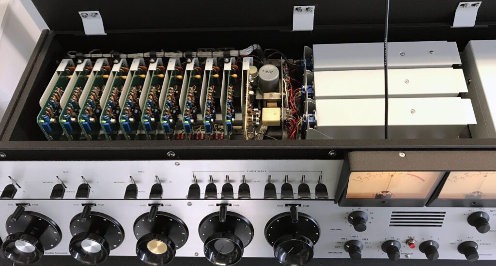
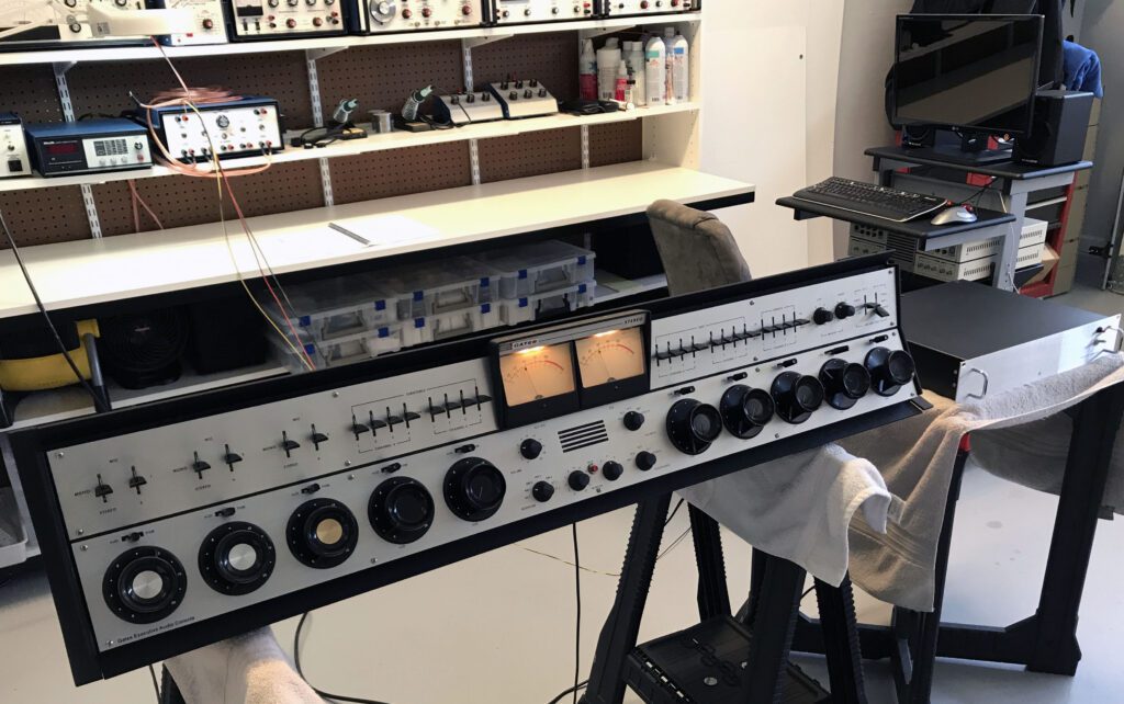
This was a big day for the console as the power supply was reinstalled and power was applied, most likely for the first time in many years. As planned, power was applied to one module at a time. As each module was connected, the current drawn from the supply was measured and compared against the typical operating current as documented in the user manual.
No problems were discovered, although two wires were left unconnected because it is unclear what function they serve. I’ll figure that out later.
The power supply performed well under load. There was essentially no change in the output of the regulated supply from no-load to full-load. The board ran for a couple of hours to confirm that things were OK.
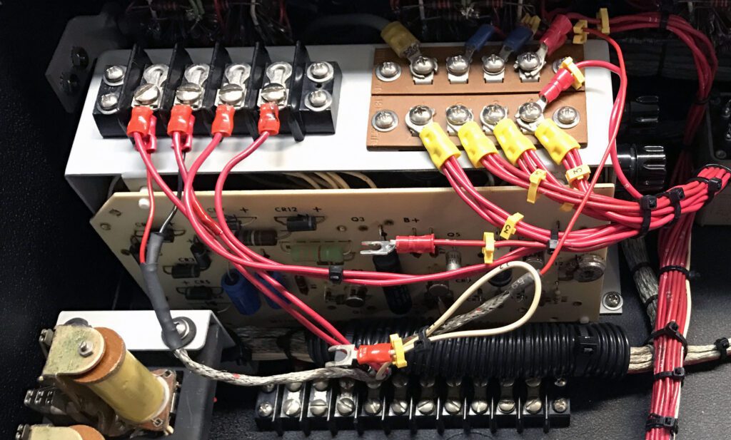
I did notice one issue that, fortunately, was easily addressed. The defective transistor discovered during initial tests of the power supply was hot. None of the other transistors, including the TO-3 series regulators, ran hot. I added a small press-on heat-sink and the device then ran warm, but not hot.
It is possible that excessive heating caused the failure of this transistor in the first place years ago. In any event, I will keep a close eye on the supply—but so far things look good.
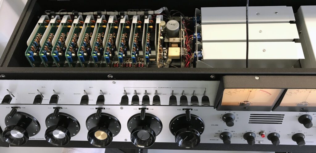
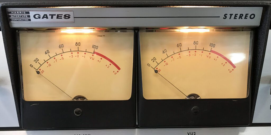
With power on, the VU meters light up. You’ve gotta love that.
While reinstalling the power supply, I took the opportunity to document the wire numbers for each module power input. This information may be useful later.
In the coming days, the performance of each module will be examined, and a full range of tests will be run.
Day 16 – Audio Through the System
The first audio signals were passed through the console today, and preliminary tests were run. In addition, the functionality of all modules was confirmed. Frequency response met the published specifications, but a high noise floor prevented accurate THD and IMD measurements.

The noise was traced to the power supply. Additional filtering on the output of the supply helped (it also reduced the transistor heating noted above), but was not sufficient to solve the problem.
As it sits, the noise floor is down about 40 dB relative to the nominal output of +8 dBm. Additional work on the power supply is planned, notably replacement of the main filter capacitor. Unfortunately, this will require removal of the supply.
Despite the setback, it was great to have audio passing through the system, from mic input to line output.
Day 17 – Working on the Power Supply (again)
While troubleshooting the power supply ripple problem, I discovered that the connector for the left channel line amplifier was intermittent. This was not the cause of the noise problem, but it apparently was sufficient to cause the power supply to fail. With no input audio, each line amplifier draws about 100 mA. This intermittent connection evidently led to voltage spikes on the supply line that damaged a number of components in the power supply.
I had previously wondered why the transistors and zener diodes in the power supply were socket-mounted. Now I understand why. When the supply fails in this manner, it destroys multiple devices. The traditional troubleshooting method of replacing one part at a time is a hit-and-miss proposition here.
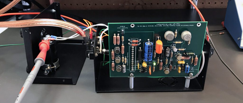
After spending a day trying to get the supply to work again, I decided to simply build a new power supply using modern devices. I settled on a design using the LM337 negative voltage regulator. The new supply is the same physical size as the original unit and has the same pin-out. It features greater output current capability, uses one-third of the parts, and is far more robust against failure than the original unit. Also, the supply is designed so it can be replaced in the field in minutes.
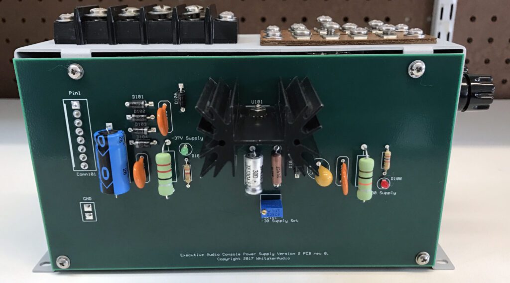
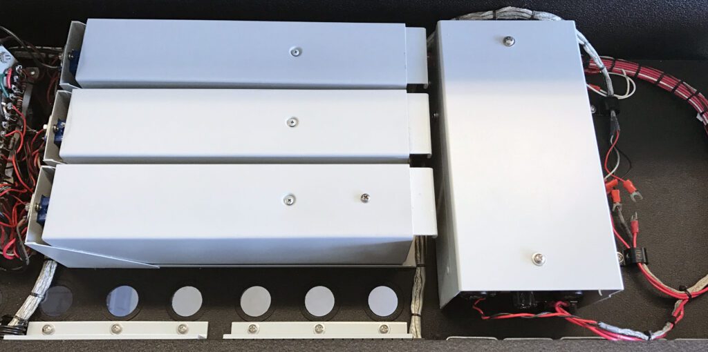
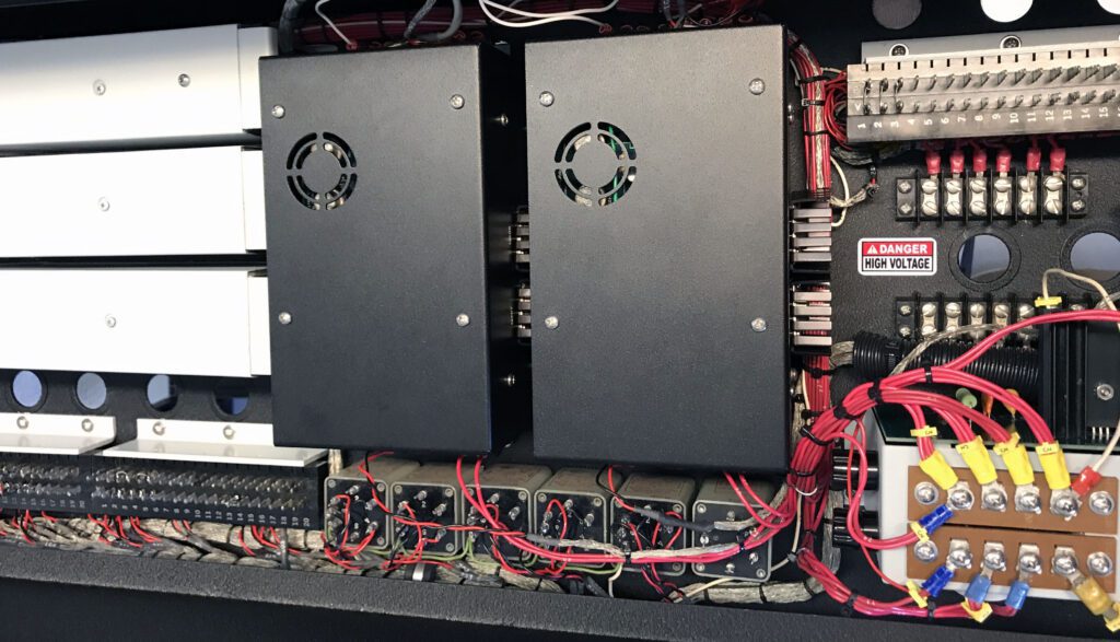
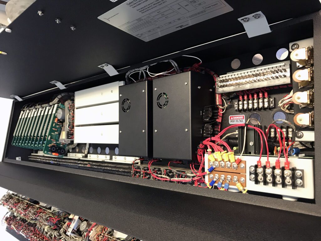
The new power supply is shown above. The design is simple and straightforward. An over-sized heat sink was used to ensure ample operating margin. The TO-3 transistors of the old power supply were not needed, and were therefore removed. The covers shown in the photo below are strictly for appearance.
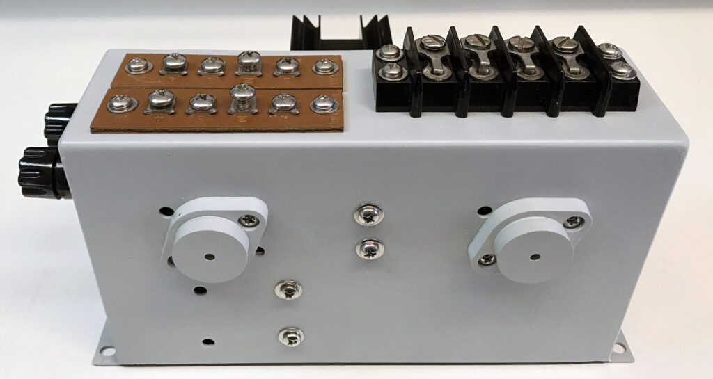
Nearly all of the components of the new power supply are contained on the PCB. Connections to chassis-mounted devices and terminal strips are made via a Molex connector. The entire circuit board can be swapped out in minutes, making field repair much simpler and faster than with the old design.
It was my goal from the start to keep the Executive console as “original” as possible. I really wanted to get the old power supply to work, but at a certain point it is best to cut your losses and go in a different direction. One of the major problems is that circuit boards of 1960s and ’70s vintage are very unforgiving of rework and repair.
Today I installed the new power supply and it works well. The noise problem is gone and the supply is stable.
Day 18 – Testing Resumes
With the power supply problem behind me, detailed proof-of-performance testing was done today on the preamplifier circuit boards and the program line amplifier modules. With a couple of exceptions, all of the circuits met or exceeded their original specifications. The exceptions were limited in scope and will require some additional work. However, none are show-stoppers.

Most of the tests on the console are performed with an Audio Precision System One automated test set. The performance of each sub-assembly is being documented in an updated user/service manual that I am preparing. The manual will include all of the wire number information I have been able to collect during this project. Having a list of wire numbers and their functions has proven to be very helpful in the restoration work.
One item that is giving me trouble is the cue amplifier. That particular board has had a rough life, with considerable repair done over the years. I may remove the cue board and do some bench work on it. But, that project can wait for a while.
With successful completion of the new power supply, I am beginning to work on designing a replacement circuit board for the microphone preamplifiers. My plan is to replicate the original Gates design, consistent with the availability of parts. I already know that the input transformer is going to be a challenge.
Day 19 – The Nameplate Arrives
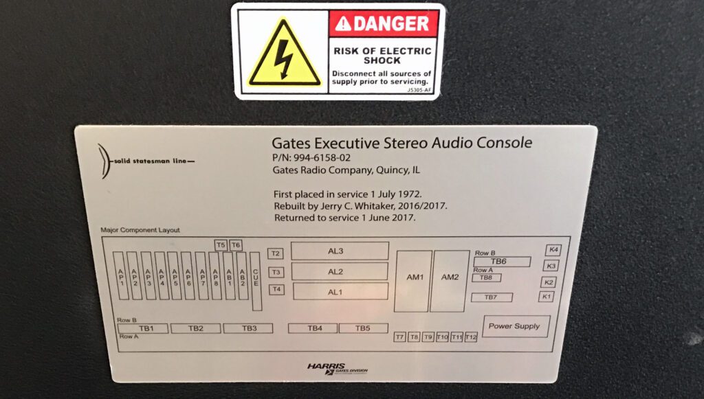
The nameplate for the console arrived today and was installed. The nameplate (shown below) includes a diagram of the major components and connection points. It is made of brushed aluminum. The piece was produced by Metalphoto of Cincinnati, which I have used in many other projects for replacement front panels.
Also, the cue amplifier is working. The problem turned out to be a faulty transistor on the cue amplifier circuit board. Basic functional tests on the cue system indicate everything is operating properly.
With the experience of repairing the cue amplifier board by replacing a plug-in transistor, I am beginning to appreciate the benefits of using sockets for the transistors. I would probably not build a new board with sockets, however.
During crosstalk tests on the microphone preamplifiers, I discovered a curious modification that mixed the left and right channel inputs through a 20 dB pad when the channel was switched to STEREO. That didn’t make much sense to me, and so I returned the circuit to the original Gates design.
In addition, a modification was found to the Network input that took the mono source and delivered the signal to both the left and right channels, but with a difference of about 3 dB. That didn’t make sense to me either, and that circuit was returned to the as-designed configuration.
At this point, I believe that I have found and removed all of the changes done in the field over the years, and the console is back to the original configuration.
The design has been finalized for the replacement preamplifier circuit boards. A replacement input transformer has been identified that should provide equivalent performance to the original transformer, which is no longer available.
Day 20 – Sounding Good
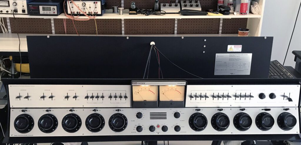
Another big day for the restoration project. For the first time, audio programming was sent through the console and reproduced on the left channel monitor speaker.
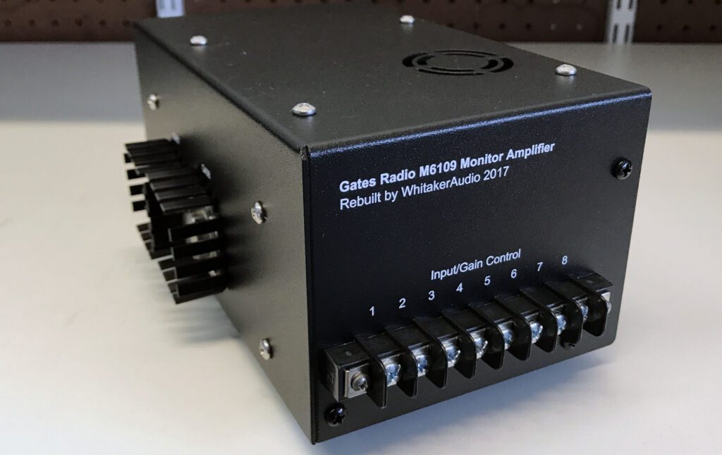
After a long search, a monitor amplifier was located on eBay. The unit was in relatively good shape when it arrived. The circuitry was removed from the cabinet, and the cabinet was sandblasted and refinished to match the other modules in the console. The circuit board was thoroughly cleaned, and electrolytic capacitors were replaced as needed.
The monitor amplifier is shown above. Testing has been limited to feeding program material to the console and listening on a speaker (which, of course, is the ultimate test of a monitor amplifier). A formal proof of performance will be conducted later.
The search continues for a second monitor amplifier, which will complete the console.
The first of the new preamplifier boards has been produced and preliminary tests have been run. Final testing cannot be completed until the input transformer arrives (it was back-ordered).
A couple of troublesome issues were resolved today. One involved a level mismatch among the three output channels. That was addressed by modifying one of the VU meter pads. The other issue involved a significant level mis-match between two settings for the right channel line amplifier input. That was addressed with a modification to an attenuator pad feeding the input switch.
In both cases. the reasons for the changes and the parts used were documented so that an engineer at some point in the future will understand what was done and why.
Day 21 – Replacement Preamplifier Boards
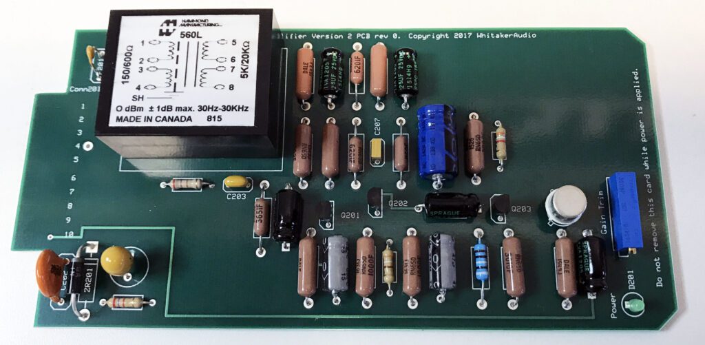
The first replacement preamplifier board was tested and installed today (see the photo below). Performance was very good, exceeding the original equipment specifications. However, like many initial versions, this one had a problem too. If you look closely at the bottom left corner of the photo, you will notice a couple of capacitors and a 5 W zener diode. The lead of the zener diode extends to near the edge of the board. When the board is inserted into the card cage, the lead from the zener diode can come into contact with the metal card shelf rail, which shorts the component (and the V– supply) to ground.
So, another version of the card was produced, this time with generous clearance between components and the edges of the board. The new PCB is a four-layer board. In the second version, card-edge finger traces are placed on both the foil side and the component side, which doubles the connection surface. This is important since some of the mating connector plating has deteriorated over time. In addition, the new board is slightly thicker than the original, which makes for a tighter (better) match with the card cage socket.
The updated preamplifier board is shown below.
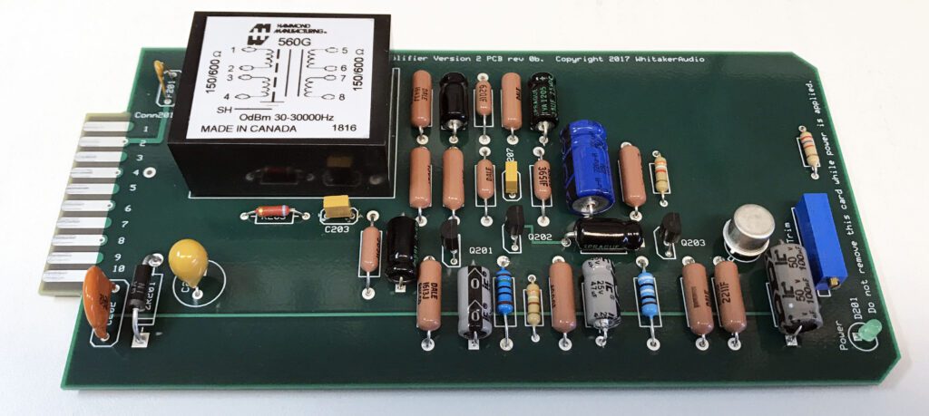
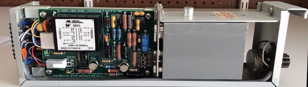
In order to get the best test numbers, it was necessary to change the values of some resistors in the input stage in order to accommodate the new input transformer. The transformer (Hammond 560G) is not a perfect match to the original. However, with the component changes it performs very well, easily meeting the original equipment specifications.
Comparing the performance of the original board and the replacement board, the usual figures of merit (frequency response, phase shift, THD+N, IMD, power bandwidth, linearity, and noise) were closely matched. The major difference was input/output phase shift. The original board has a phase shift ranging from –30 degrees at 20 kHz to +30 degrees at 20 Hz, referenced to 1 kHz. The new board has a phase shift ranging from –15 degrees at 20 kHz to +30 degrees at 20 Hz, referenced to 1 kHz. Because of the differing phase shifts, an old board and new board should not be used in the same microphone channel.
Day 22 – Replacement Preamplifier Boards Installed
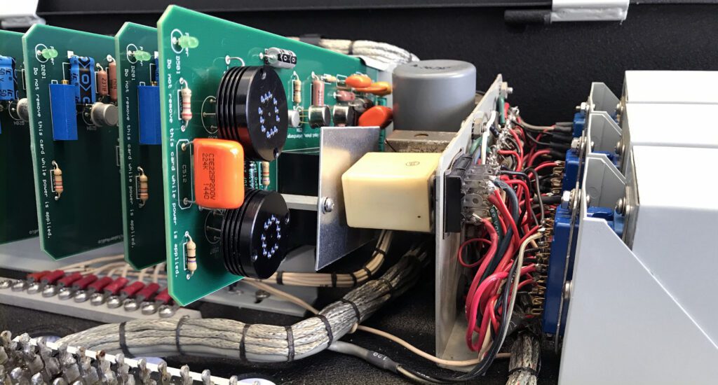
The replacement preamplifier boards have been completed and all 10 have been installed in the console (as shown below). If you look closely at the far right side of the card cage, you will see the original cue amplifier. A new circuit board has been designed for that amplifier and will be assembled within the next couple of weeks. As with the replacement preamplifier board, the replacement cue amplifier will be identical to the original Gates design, except for part substations where needed. The only other change from the original design is the inclusion of a resettable fuse on the V– input and some on-card power supply filtering on all boards.
In a major step toward completion, work on the front panel has been finished. As stated previously, the upper aluminum panel was in good shape, but the lower panel was scratched and had three extra, unused holes drilled into it. So, replacement of the lower panel was the only solution.
I used the vendor ProtoCase to produce the piece. It was a very difficult project because every hole needed to be exactly duplicated on the new piece, or the whole thing would be useless. I developed an AutoCAD drawing of the lower panel, along with detailed dimensions and the necessary labeling.
When the panel arrived, it was very close. Unfortunately, it was not close enough. I could have made it fit by drilling-out some of the switch holes, but that was a poor solution. Instead, I made the necessary changes to the AutoCAD file and the vendor produced another version. This one was perfect.
The panels are brushed aluminum with a clear anodized finish and lettering silk-screened onto the piece. The upper and lower panels look almost identical. Unless you examine them closely, you wouldn’t know that one was produced 50 years earlier than the other.
Another project that ProtoCase took on was to refinish the round dials for the fader knobs. They were sandblasted and powder-coated, and then the lettering was silk-screened to make the finished piece.
The original fader knobs were in good condition, needing only a thorough cleaning. The colored inserts added by some stations had faded over the years. They were all removed, except for two silver inserts and one gold insert, which were placed on the microphone channels. I will probably have the inserts reproduced in a couple of colors, but that can wait until just before the board goes into service.
Day 23 – The AC Power Supply
As mentioned previously, the Executive console requires an external ac power supply to function. Three 28 V ac circuits are needed—one for the card cage and program amplifiers, and one each for the right and left monitor amplifiers. The ac supply was not included with the console when purchased on Bay. Fortunately, the requirements are easily met with three low voltage transformers.
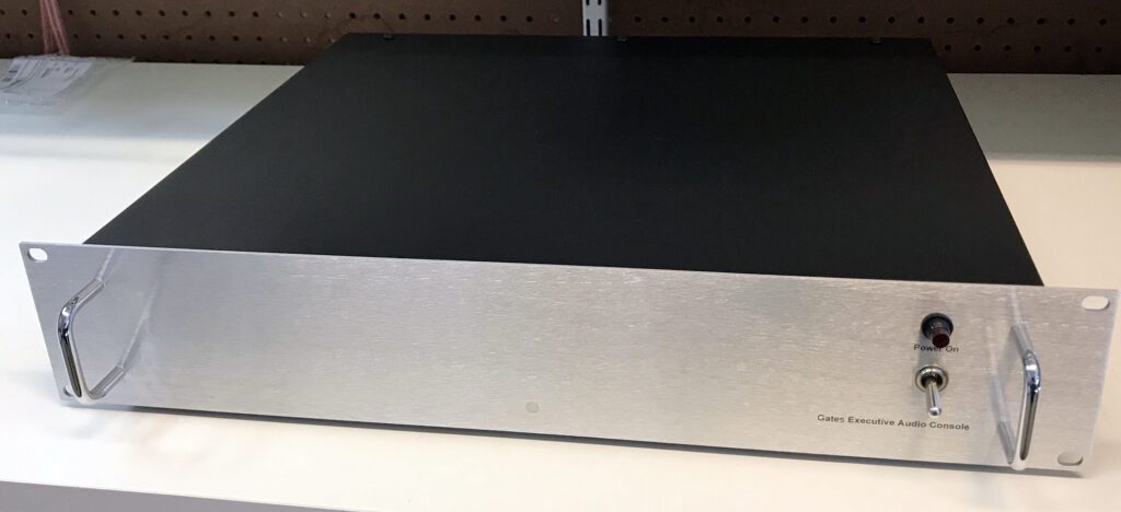
The original supply was modest in construction; essentially a panel with transformers mounted on it. For the rebuild, however, I decided to produce a more polished supply, as shown above. The 19-inch rack-mount chassis was produced by ProtoCase using their ProtoCaseDesign software. The end result was very good.
I maintained the style of the Executive console with a brushed aluminum front panel and black textured powdercoat finish.
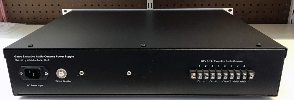
The three independent 28 V ac circuits are fed by a power conditioning system that includes surge limiting, filtering, and overload protection.
The ac power transformers are mounted external to the console in order to reduce hum in the system. The supply is typically mounted in a rack cabinet near the console. Separation of up to 10 ft is easily accommodated.
Day 24 – Final Tests on the Preamplifier Boards
Work was officially completed today on the new preamplifier boards. All 10 are installed and working correctly. Performance meets or exceeds the original Gates cards. The new power supply board also works well, easily handling the current load with all preamp cards installed.
While checking the operation of the microphone channels, I was surprised to find another maintenance error from the past. (After all these months, I thought I had found all of them.) There are three stereo microphone mixer channels. The channels can optionally be switched to Mono, where the Left channel signal is fed to both program channels. While checking the new preamplifier boards, it was evident that the Mono circuit was not functioning properly on Channels 2 and 3. After several hours of troubleshooting, I found that the mixer attenuators for Channels 2 and 3 had been wired in reverse, with the Left channel feeding the Right, and vice versa. Both attenuators had been replaced at some point in the past, and the wiring error was presumably created at that time. Regardless of when it happened, now it is fixed.
Day 25 – Replacement Cue Amplifier Completed
The replacement cue amplifier circuit board was completed today and installed in the console. Like the new preamplifier cards, the cue amp is functionally identical to the original Gates board. Performance of the two cards is very close. Specific changes to the original design include: 1) power supply filtering on the card, 2) inclusion of a resettable fuse on the V– input, and 3) modified frequency response.
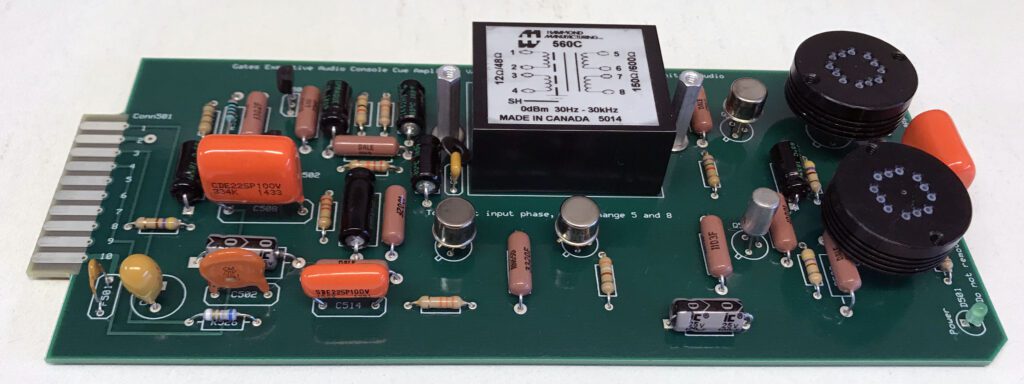
In the original Gates circuit, frequency response is rolled off sharply below 300 Hz and above 6 kHz. This was done in recognition of the primary function of the cue amplifier—voice communications. For the new card, the response curve was broadened somewhat to provide improved fidelity. The trade-off is slightly lower overall gain; however, this is not an operational issue since the cue circuit has ample gain.
The new cue amplifier board is shown above. Note the oversized heat sinks on the two output transistors. The original heat sinks were rather modest in size, and in bench tests one of the output transistors on the prototype board failed during power bandwidth testing (this testing mode pushes the operating limits of the circuit). It is not easy to find heat sinks for TO-8 devices, but a search on eBay did the trick.
In the photo above, an aluminum shield can be seen mounted above the input transformer. An examination of the photo shows a plug-in relay directly opposite the input transformer. This is the intercom Talk/Listen relay, which places the cue amplifier output contacts adjacent to the input transformer. The shield prevents feedback and noise from impacting operation of the cue circuit.
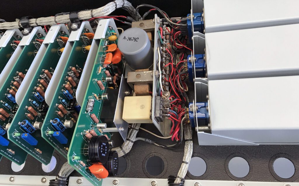
The photo above shows the completely rebuilt card cage, which contains the preamplifier boards and the cue amplifier. When fully loaded, the card cage pulls about 300 mA from the power supply with no audio input (200 mA from the –30 V regulated supply and 100 mA from the –37 V unregulated supply).
The addition of resettable fuses on all circuit boards is intended to avoid a complete shutdown of the console in the event of a failure on any one board. This is very important, of course, for on-air reliability.
The value of the resettable fuse was demonstrated during initial testing of the prototype cue amplifier board. As mentioned above, one of the output transistors failed during testing to determine the maximum output capability of the circuit (power bandwidth). The resettable fuse did not prevent the transistor failure (that was caused by excessive operating temperature) but it did prevent collateral damage caused by the failed transistor.
In a previous failure of the original cue amplifier board, two resistors in series with the output transistors failed rather spectacularly when one of the output transistors failed. The resistors, in fact, left burn marks on the board as evidence of the problem. Now, however, with the resettable fuse in place, the current draw was limited and damage to additional components was avoided.
Day 26 – A Great Find on eBay
Thanks to a lucky search on eBay, I was able to repair one of the Audition/Program lever switches on the front panel. The Channel 3 microphone input worked fine in the Program position, but not in the Audition position. The cause was a broken element within the lever switch. This type of switch is typically quite reliable; however, this one had failed at some point in the past. Someone had attempted to repair it, but the fix did not hold.
I was able to find a similar lever switch on eBay, and because of the structure of the switch, replacement of the broken element was possible. This was, admittedly, a long-shot, but fortunately, the repair job went very well.
Meanwhile, work has begun on replacement monitor amplifiers. As mentioned previously, the monitor amps were missing when I bought the console on eBay. I was able to find one monitor amplifier, but of course two are required for stereo. So, replacement units have been designed (based on the original Gates units) and are being produced.
Day 27 – Replacement Monitor Amplifier Modules
The first of two replacement monitor amplifiers was completed today. The circuit is identical to the original Gates M6108A monitor amp, with some updates. The amplifier board is shown below undergoing performance testing on the bench.
The new version of the amplifier includes an optional circuit intended to limit current through the output transistors when the unit is over-driven. The current-limiting option was included in some later versions of the M6108.
The completed unit is shown below. The cabinet is the same physical size as the original Gates product, in order to fit into the Executive console. After testing has been completed, a second unit will be built. The one original Gates monitor amplifier will be taken out of service and retained as a replacement device, should it be required at some point in the future.
The cabinet for the replacement amplifier was produced by Protocase, using their design software. The results were very good. Improvements on the original cabinet design include large heat sinks for the TO-3 style output transistors and ventilation for the TO-8 driver transistors. Connection points are identical to the original amplifier in order to make installation in the Executive console straightforward.
The additional cooling of the output devices is particularly important for performance testing at full power, which generates a large amount of heat in the output transistors.
The new circuit board is sized to be an exact replacement for the original Gates board. The updated board, thus, can be used either to refurbish an existing M6108 or to build a new unit.
In parallel with work on the monitor amplifier, a replacement upper front panel is being designed. As noted in a previous blog entry, the original upper panel was in relatively good shape. The new panel is being produced in order to change some of the channel assignments. This is strictly a labeling change; none of the circuitry will change.
Day 28 – Front Panel Replacements
I have finished a first pass on the replacement upper front panel. A representation of the panel is shown below. The two large holes in the middle are where the VU meters go.

For reference, the lower panel is shown below.

My plan, at this point, is to have a new panel made, rather than have the existing panel refinished and relabeled. By the time I ship it off to the vendor and they prepare it for finish and printing, the cost of using the existing panel will match (or perhaps exceed) just starting from scratch.
Day 29 – New Monitor Amplifiers Installed
The new monitor amplifiers were installed today. This completes work on all of the major sub-assemblies. Minor repairs will be taken on as identified; however, all circuits are now installed and working correctly.
After the replacement upper panel is produced, wiring for remote start functions will be installed. The system will provide contact closures when the turntable channels are switched into Program or Audition. This function will be accomplished using available contacts on the channel lever switches.
After the console has been completed, work will commence on a stereo turntable preamplifier. Two preamps are planned, with the possibility of a third.
In a parallel track, the studio that will house the Executive console is being designed. Construction of necessary furniture is expected to begin in December 2017.
Day 30 – Nearing Completion
With installation of the replacement upper front panel, the console is ready for service.
At the beginning of this project, I estimated July 2017 for completion. So, I met the project time-line. Having said that, I have several other pending projects related to the console, including:
- Working with FastSigns to reproduce the colored circular inserts for the mixer channel knobs.
- Rebuild the three line amplifiers. Thanks to some recent work, all of the line amps now meet the new equipment specs. However, the noise performance is a bit lacking, and they are the only active circuits that are original (that would make them about 50 years old). I have ordered parts for the first of two stages of work.
- Build two stereo turntable preamps based on a classic Gates design.
Next up, I plan on checking each attenuator (mixer fader) and cleaning them up as needed. All 10 are in good condition; however, they require service from time to time. I have found two replacement attenuators and refurbished them as spares.
Day 31 – Updated Line Amplifiers Installed
Progress continues to be made on the updated line amplifier circuit boards. Shown below is the new output PCB. Note the oversized heat sink.

The line amplifier module is made up of two circuit boards: the driver and the output. The new boards are the same physical size as the originals, and function the same. The major difference is the use of plug-in Molex connectors for the interconnecting wiring. This makes for easy service, if required. One of the completed modules is shown below.
In addition to replacing the circuit boards in all three modules, the plug-in connectors were also replaced. In a couple of instances, the contacts had deteriorated over time. Fortunately, exact replacement connectors were available. In one case, the mating receptacle on the mounting tray was replaced as well.
A replacement cabinet for the program amplifier was designed, but not produced, since three of the original modules were available. Should the need arise, however, a replacement cabinet is ready to go.
In the course of building replacement circuit boards for the console, I have in all cases built a spare board. The cost increment to build the additional boards was small, and having spares on hand going forward makes it possible to return the console to service quickly if a failure occurs.
Day 32 – Replacement Lever Switches
In a lucky find, I was able to locate exact replacement lever switches for the upper front panel. These two-position lever switches are used extensively on the console (the entire top row). The switches have self-wiping contacts that tend to self-clean with use.
Over time, some of the switches had been damaged or otherwise were in poor condition. The main problems were with the three microphone channels, which had been modified in the past (as documented previously). The reliability of a couple of the switches was marginal, and so all six microphone input switches were replaced.
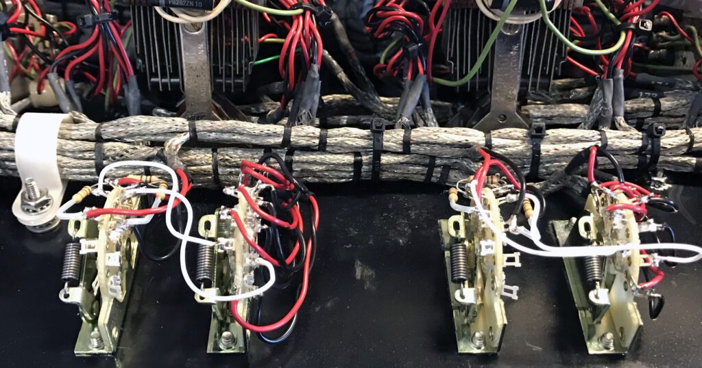
The new device, made by Electroswitch, is an exact replacement. The mounting holes are identical. The switches are available by special order only, and are rather expensive. However, having switches available for replacement is very important since repair of the device is quite difficult. The photo above shows four of the new Electroswitch devices installed in the console.
Final steps in the Executive audio console project included a complete proof-of-performance for the unit and detailed documentation of major functions. A part of this effort included confirmation that all signal switching systems worked as intended, and that all levels were within specifications. Some minor fixes were made here and there, but largely everything checked out perfectly.
Day 33 – Project Completed
Work on the Gates Executive Stereo Audio Console is now essentially completed. The unit is fully functional, and all active circuits have been updated. This project started off with no firm time line or budget. As it turns out, the time line was almost exactly one year. As for the budget, well that was a bit of a surprise.
Looking at the big picture, I have kept detailed records on what each element of the rebuild project has cost. The following represents the bill of material (BOM) costs, not including shipping, tax, time, labor, and NRE expenses (e.g., prototype boards and remade parts).
- Cabinet/chassis work = $1125
- Upper and lower front panels = $1100
- AC power supply and –30 V regulated power supply = $1749
- Preamplifier = $158 per board for a run of 10 boards
- Program amplifier = $605 per unit for a run of three
- Cue amplifier = $304 per board
- Monitor amplifier = $498 per unit for a run of two
Frankly, I have been stunned at how much this stuff has cost ($6,854.00). The major expenses are the cabinets (for the main chassis, AC power supply, and monitor amplifiers), circuit boards, and audio transformers. Purchasing the Executive console on eBay was the cheap part!
These expenses do not tell the entire story. The NRE costs have been significant—on the order of 50% the production costs.
Still, the time and money have been well spent. The console is in superb shape and the studio where it will reside is nearing completion.
Postscript
The Gates Executive Audio Console has been installed in Studio Two of Post Audio in Sacramento, CA. The studio will be used for doing live podcasts of the Vinyl Snob program. See www.vinylsnob.com.
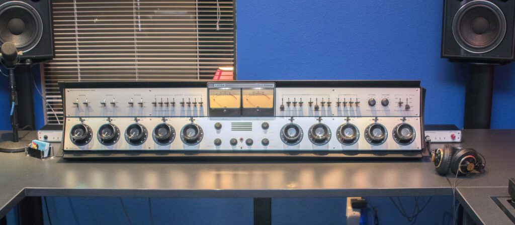
Shown above is the console on installation day. Detailed documentation on the Studio Two installation is also available for download.
Available Downloads
As documented above, it was necessary during restoration work on the Executive Audio Console to remanufacture several circuit boards used in the console. The new boards maintain plug-in compatibility with the the original boards but utilize modern components. The original circuit design is maintained, with the addition of several changes intended to improve reliability and performance.
Documentation and project files for the work described in this blog are available for download at no charge. Please see the Available Downloads blog on this web site.
This restoration project was a lot of fun, and I learned a great deal during the process.
But wait, there’s more. See the Gates Executive Audio Console Restoration, Part 3 blog.