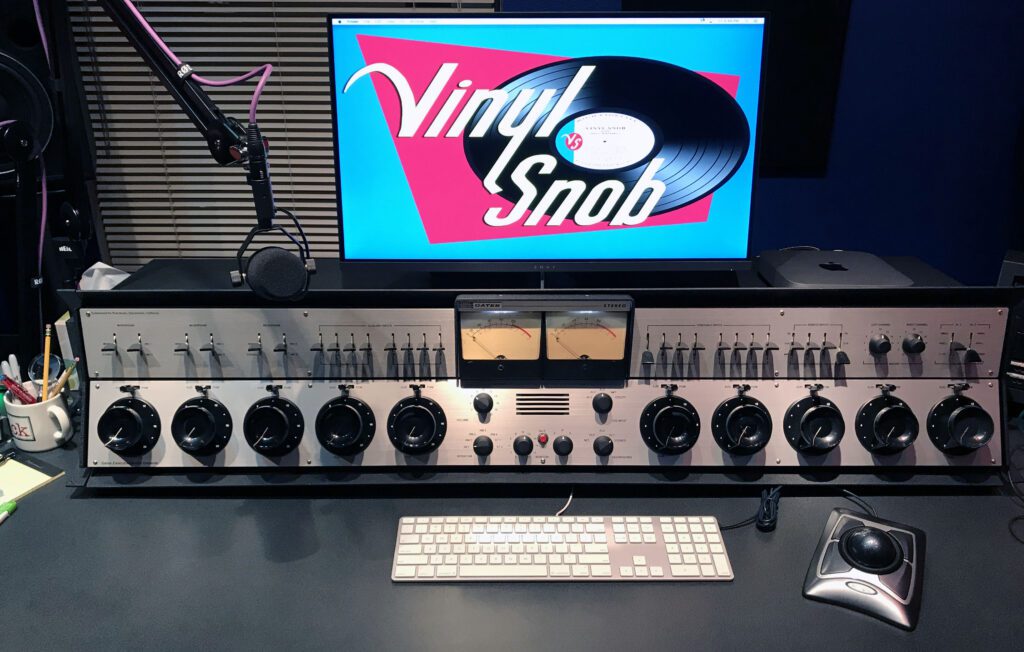
Gates Executive Audio Console Restoration, Part 1
The Gates Executive Audio Console was a favorite of radio stations in the 1960s and 70s. This blog catalogues a complete rebuild of the classic on-air board. What started out as an eBay fixer-upper is now back in the studio.
The console was in generally bad shape when acquired. The eBay listing was “for parts, not working.” That’s never a good sign. However, all of the major components were there and documentation on the console was readily available.
This project was fortunate in that there was no deadline for completion, and for all practical purposes no maximum budget. So, it took on a life of its own.
The project stretched nearly two years. About a year was spent rebuilding the Executive console and another year was spent installing the unit, optimizing it, and adding auxiliary equipment.
In the blog entries below, we chronicle the process from “sold as-is, local pickup only” to being back on the air.
Background – How the Project Started
The restoration project began in October 2016 when my brother, who at the time ran a recording studio in Sacramento, CA, suggested it would be fun to set up a 1970s-era radio station control room for special projects and, well, just because we could. His studio has all the cool new stuff you would expect in a modern recording facility, but since we both worked in radio back in the day (he in front of the mic and me behind it), we both have more than a little nostalgia for the younger days of radio (when, coincidentally, we were both younger).
So began the search for a classic radio audio console. At the risk of generalization, there are about four basic classes of audio consoles used for radio broadcast applications, and they can be roughly divided by the era in which they were made:
- Pre-1960: tube-type mixers of limited capabilities and modest performance.
- 1960 to 1980: transistorized mixers with considerable flexibility and good performance.
- 1980 to 2000: mixers built using integrated circuits and discrete semiconductors offering considerable flexibility and high performance. This class of mixers ushered-in the era of the mixing desk—the mostly flat console with long-throw linear faders. Ubiquitous.
- 2000 to present: computer-assisted or computer-based mixing systems where the work surface is essentially an input device to the computer.
We focused on the 70s style, since it represents, arguably, the golden age of radio—a time when radio was at its peak in terms of influence (before the CD, Walkman, iPod, satellite radio, and web streaming). Having arrived at the era we wanted, the search began for the centerpiece of the project. Because of the size and weight of these audio consoles, shipping is problematic. Therefore, the eBay selection was immediately narrowed to “local pickup.” After about a year of casually looking, we found a very good candidate for sale at a reasonable price. It was about a 4 hour drive from home to pick it up, but it was worth the trip.
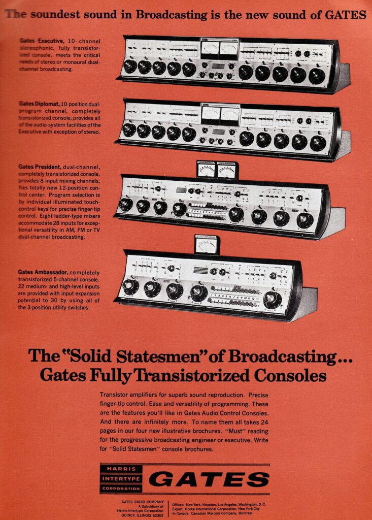
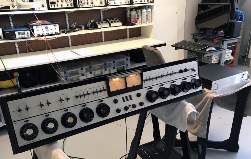
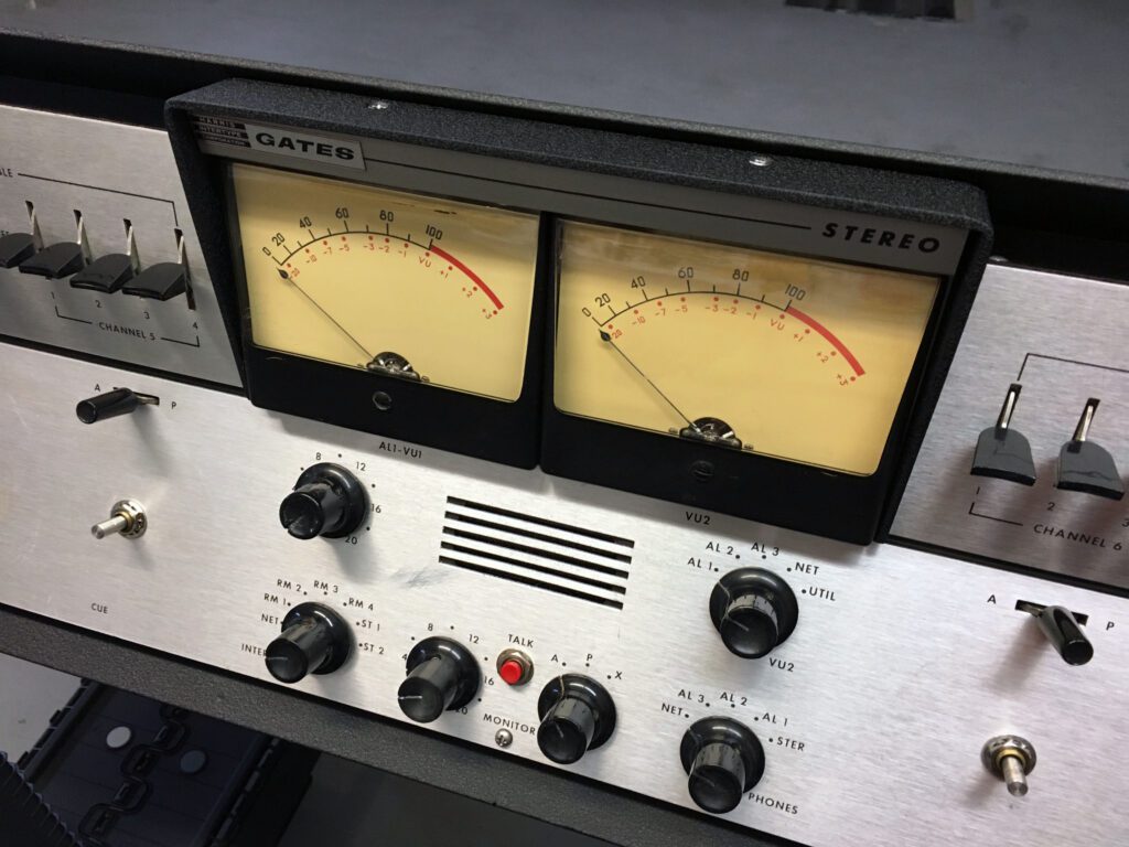
The board we decided on was the Gates Executive Stereo Audio Console, manufactured by the Gates Radio Company of Quincy, IL. A trade magazine ad for this line of consoles is shown below. The Executive was produced from the mid-1960s into the 1970s. It was the top of the line product, offering a wide list of features and switching capabilities for the then-emerging field of stereo FM broadcasting.
Like most audio consoles of the day, various inputs could be switched into the separate mixing channels and routed to cue, program, and audition circuits. Each served a specific purpose at a radio station.
The Executive did all this and whole a lot more. It was intended to serve as a central mixing and control point for a suite of studios that included the control room and two announce booths. A full complement of resources were provided for the announce rooms, including microphone inputs, cue and intercom, monitoring, speaker muting, and “on-air” warning light control.
With 10 mixing channels, the board was about as large as practical, measuring a full 54-inches across. The series also introduced a very stylish knob, unique to Gates, that is about as ergonomically perfect as possible. The Executive was one of the largest radio consoles made by the company during the rotary pot era. The 1971 list price in Gates catalog #99 was $5,300, making it the most expensive radio console in the book. The next largest board was the Dualux II, another 10 channel mixer, also intended for combined AM/FM stereo operation.
Radio consoles during the 1970s and 80s had a dubious flirtation with push-button switches. Examples can be seen in the two smaller consoles in the ad above. Push-buttons offered a space-efficient option to the more conventional rotary switches, or the more stylish (and more expensive) lever switches (as used in the Executive console). Early mechanical push-button arrays, however, often suffered from poor reliability, and interlocking switches (where, when one button is pressed, another is automatically released) were often mechanically noisy when engaged. This was not the best situation for a live broadcast environment. So, in the search for an audio console, push-button switches were a non-starter.
A well-built lever switch has remarkable reliability. And they can be operated easily and quietly in a live radio environment.
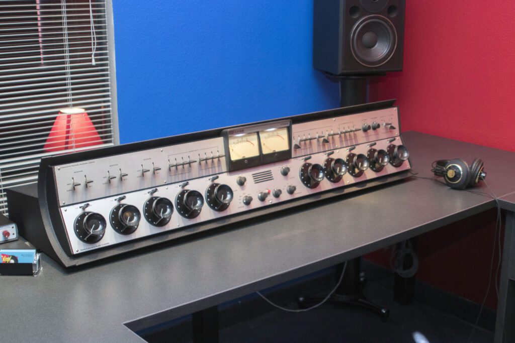
So, we were happy to find the ideal console for this project—the Gates Executive Stereo Audio Console.
Day 1 – Assessing the eBay Purchase
I have taken a close look at the board. Generally speaking, it is in reasonably good shape. However, there are four unexpected finds:
1) The power transformers are missing. They are mounted external to the board on a small chassis. These are easy to replace. And not very expensive. This is an easy fix.
2) The monitor amplifiers are missing. The photo below shows the inside of the chassis where the monitor amplifiers should be. The monitor amplifiers are used to drive the studio speakers, right and left. I have seen them for sale on eBay from time to time. The most recent posting had one for about $75. I will keep my eyes open for these.
Strictly speaking, the monitor amplifiers are not needed for operation. If powered speakers are used, the monitor amplifiers would simply be shut off. Alternately, I could build two replacement monitor amplifiers using the original Gates diagrams. So, this is fixable, but it might take some time. I think that for the sake of completeness, the monitor amplifiers should be in the finished board.
3) One edge of the cabinet trim piece is chipped. I knew that from the eBay listing, but upon closer examination it is a little more substantial than it seemed to be from the eBay photos. I’m not sure how I will fix it. There are some possibilities, but it will require a little creativity.

4) Unfortunately, somebody decided to “improve”the board at some point. The photo of the front panel below shows two issues. The first is that the Master Gain controls have been removed (see the top portion of the front panel). This is easily fixed, but matching the knobs will be a challenge. The larger issue is the three holes between mixer pots 8, 9, and 10. These are just holes. Nothing in them.
There are two options here. The first (and best option) would be to have the lower panel of the mixer reproduced. I could do that, at some expense. If I did the lower panel, I would probably want to do the upper panel as well so they both match. Now we’re talking about some serious work (and expense). The second option would be to install small push-button switches and wire them out as “remote control” buttons. The explanation would be they are connected to cart machine “start” functions, etc. In fact, that may be what was originally there. If you look at the knobs and imagine potting up #8, your thumb is in a perfect position to press “start.”
My plan is to focus first on the cabinet. The front panel will be the last thing I work on, since it is potentially the most time-consuming and expensive. Before I can work on the cabinet, I need to carve out a large working space, since when the cabinet is disassembled, I will need to spread out the inside wiring and hardware and leave it there until I get the cabinet back from the shop.
In the meantime, I will keep looking for spare parts on eBay that might come in handy. For example, it could be helpful to find a couple of extra “mixer” (big) knobs, just in case one breaks at some point.
Anyway, I am encouraged about this project. My estimate for completion is about 6 months. Right now, the biggest challenge is finding a space large enough to work on it.
This will be a beauty when it is done!
Day 2 – Restoration Work Begins
Today I began the restoration project. It’s great to get started. However, I have uncovered some very troubling items. Not show-stoppers, but they will add considerably to the task.
This board has been in service at a couple of stations, maybe more. The last installation job, regrettably, left much to be desired. It was far below what one would expect for a piece of mission-critical equipment, such as this board. I must add here that I appreciate the need for speed in some situations. And, I do not like to criticize someone else’s work. But, this is quite a mess.
Keep in mind that this board was intended to be used as the primary means for delivering on-air program material. As such, it is very important to have a quality installation job. Two of the most important characteristics of a quality installation are reliability and maintainability. Whoever last installed this board fell short on those objectives.
At the risk of over-thinking the installation work, it appears this board has been installed and removed from service at least two times. Fortunately, the mess is fixable.

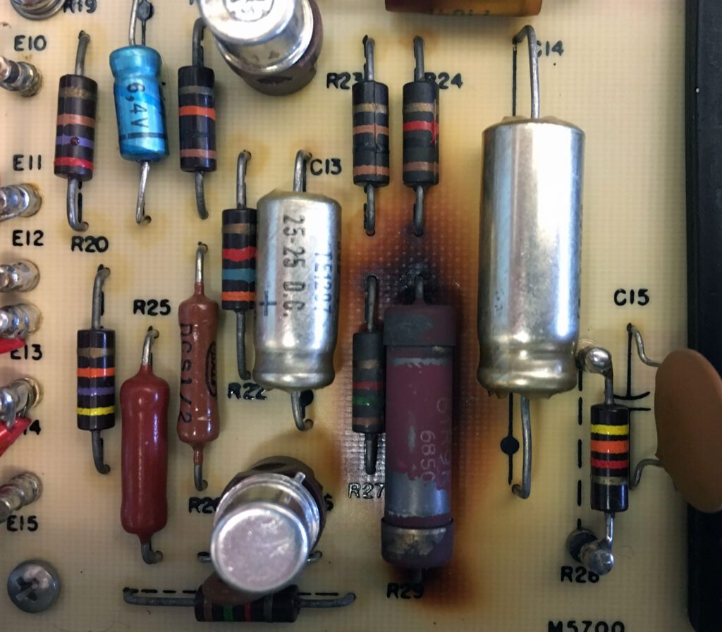
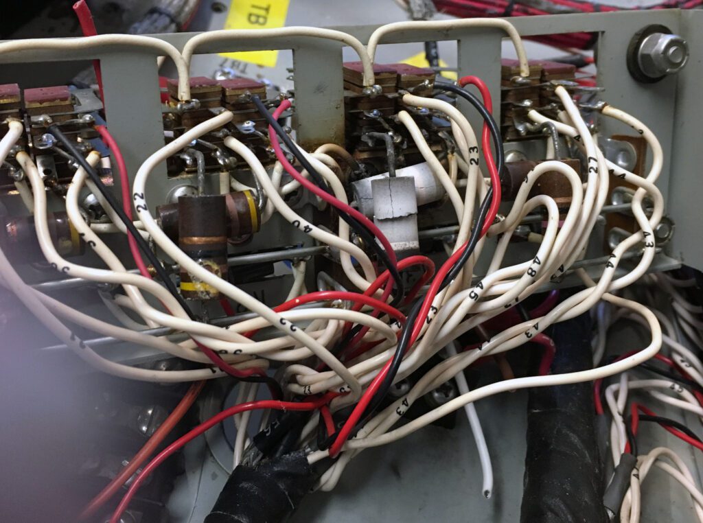
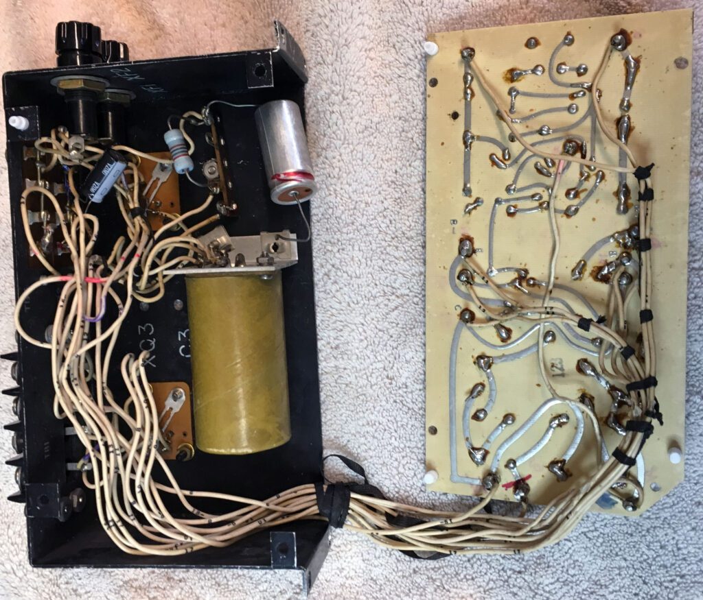
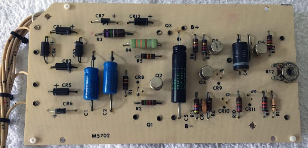
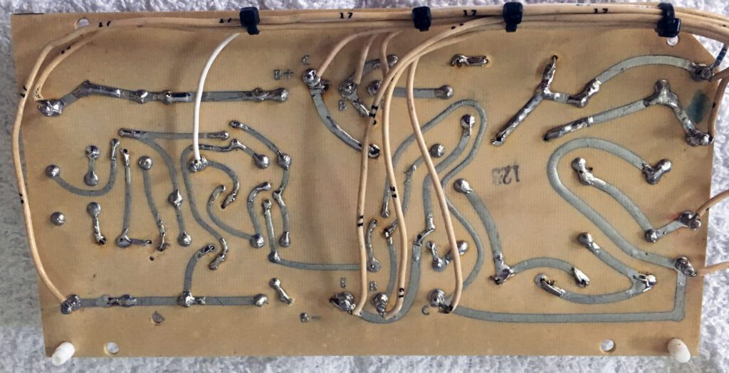
The maintenance performed on the board shown below is equally troubling. And, unfortunately, it is more difficult to fix. Notice the burnt resistors on the circuit board below. This is one of the program line amplifiers.
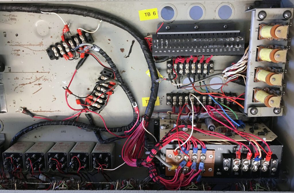
The photo below shows wiring of the power supply module. The extent of the mess in the power supply is hard to visualize from the photo. Among the notable shortcomings are at least two filter capacitors that were improperly soldered, with leads just dangling on the board. Missing components add to the issues.

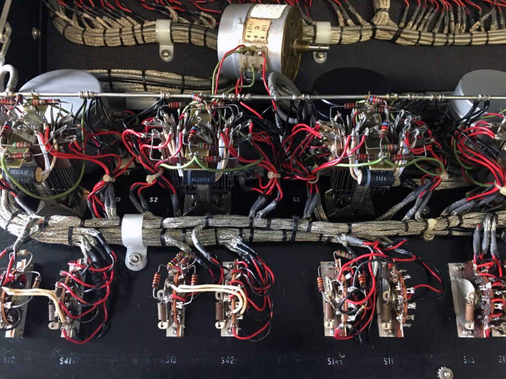
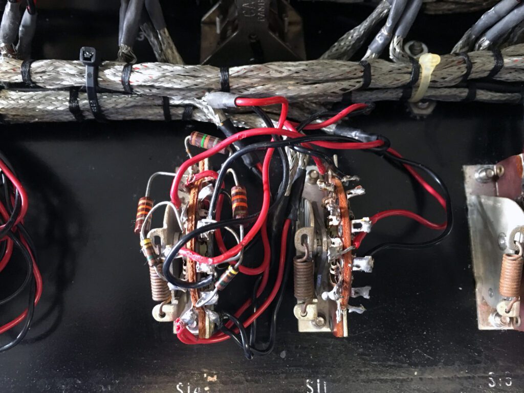
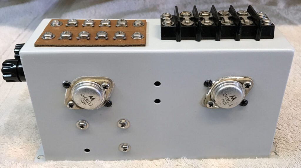
And then there are the component failures. The white items in the image below are 2 W resistors on the relay panel burned in two.
So, we have a challenge here.
It appears certain that I will need to repair or possibly re-manufacture the following circuit boards:
- Power supply
- Program line amplifier
- Cue amplifier
- Mic preamp(s)
Actually, that’s all of the boards.
This is doable, and the mixer will be first-rate when finished. However, it will take considerable time (and money).
When I remanufacture a board, there is a large amount of documentation that goes with it. So, we are talking about a month or two for each board. The major steps include design, assembly, testing, and documentation. I’m fine with doing this, and it will be a fun project. However, it blows the 6-month timeline out of the water.
So, that’s the bad news. The good news is that none of these are show-stoppers. Aside from examining all of the active circuits today, I began the process of cleaning-up the internal wiring.
Day 3 – Cleanup
Today I worked on cleaning up the external connections to the board made by somebody long, long ago.
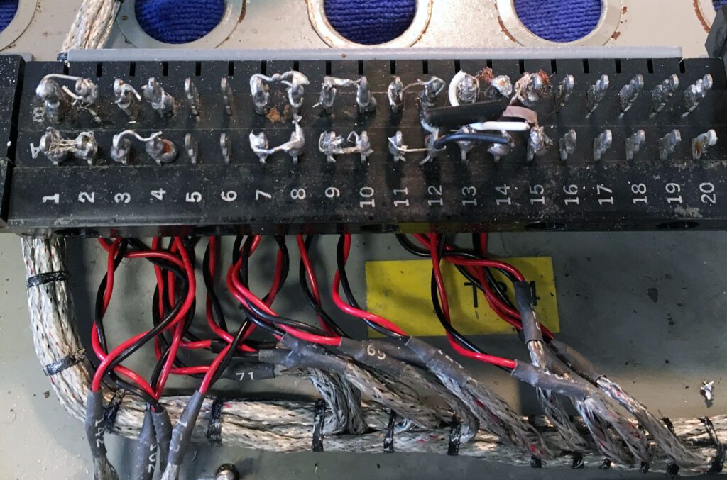
The good news is that the terminal blocks clean up very nicely and look nearly new when done, as you can see in the before and after photos.

The cleanup process was time-consuming but simple. First, the wire on the terminal was removed. Next, the excess solder was removed by using solder wick (American Beauty annealed copper, 0.130 inch). Cleaning all of the terminal posts on the board required 20 feet of solder wick. There was a large amount of solder present on nearly all terminals—far more than required. In addition, after removing the wire and excess solder, the remains of another wire were often found, indicating that the original installation wires were not unsoldered, but instead just cut off. Not the best approach.
After the remains of the old wiring and the excess solder were removed, I removed the mounting screws for each terminal block so I could position it on one side. Then, after surrounding the block with absorbent paper towels, I applied a generous amount of flux remover (MG Chemicals 413B-425G). This is a spray-on product and it does a very good job of cleaning solder flux from electronic parts. In this case, because of the amount of solder residue, it was necessary to apply several coats.
When using flux remover, it is important to contain the spray and the runoff, since the chemicals in the remover may also remove paint and silk-screened lettering. A thick padding of absorbent paper towels will usually suffice. In this particular case, damaging the cabinet finish was not a major concern, since the entire cabinet was going to be sandblasted and refinished anyway.
The flux remover made it possible to get the terminal blocks back to like-new condition, rather than just clean.
Be certain to provide adequate ventilation when using flux remover and to properly dispose of the soiled paper towels (outside the work area).
I have made an inventory of all the hardware (screws, washers, nuts, etc.) used on the chassis. I plan on tossing all of the old hardware and replacing it with new, stainless steel hardware. The cost is minimal, but the difference in appearance is significant.
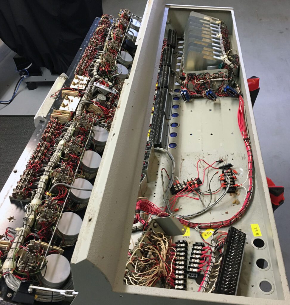
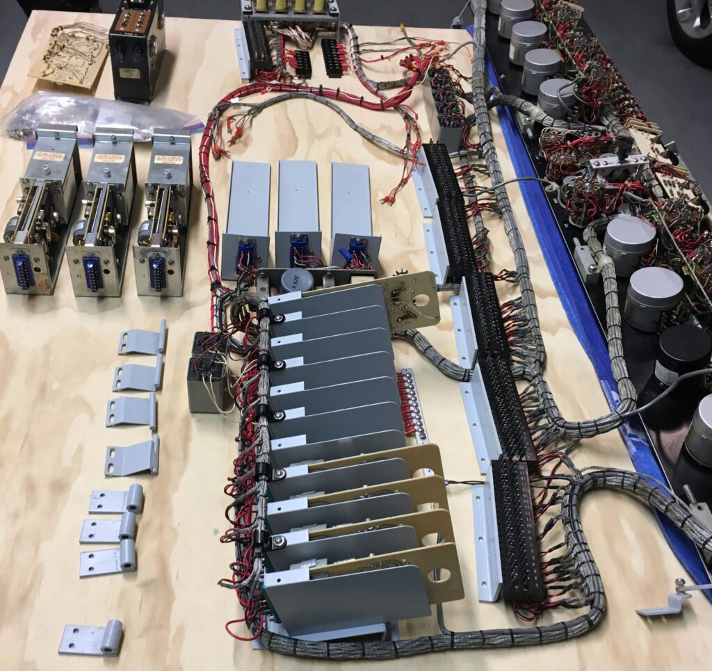
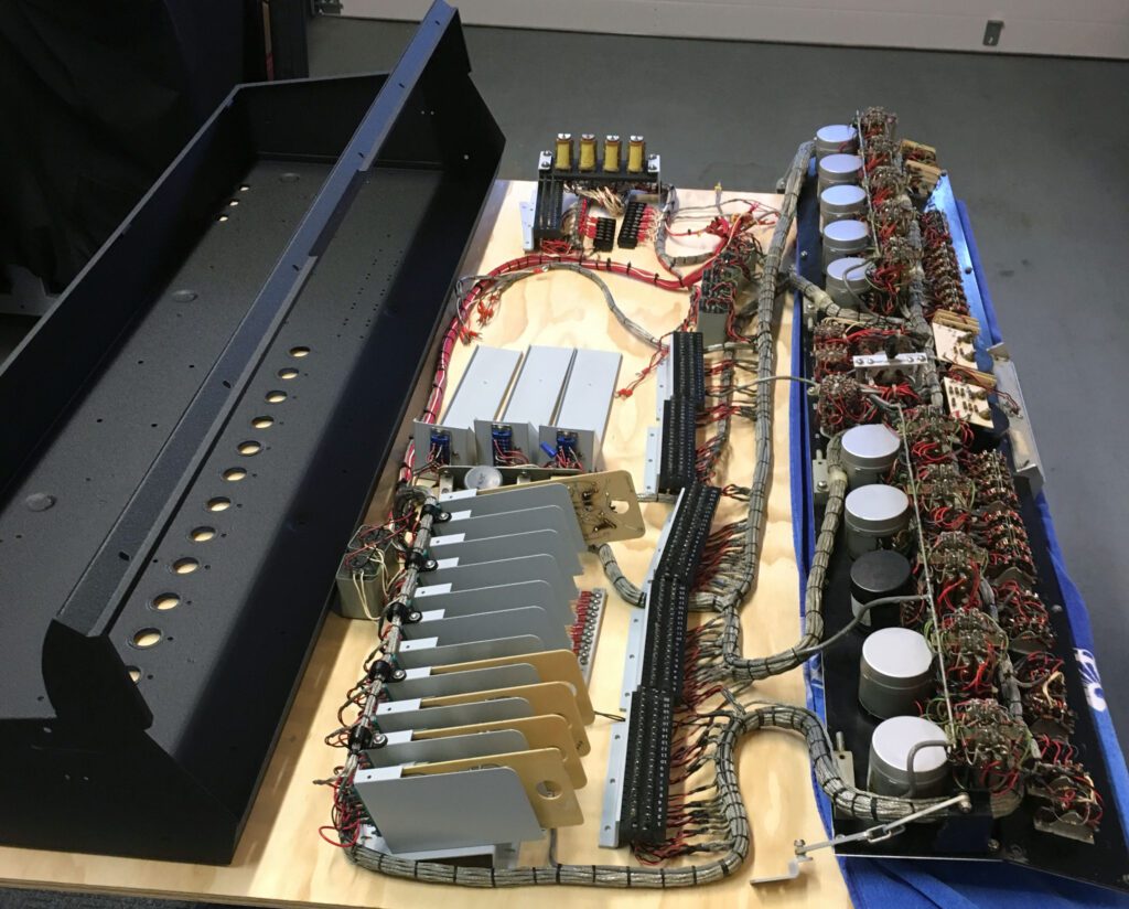
I have disconnected all of the components from the chassis, as shown in the photo below. The next step is to remove the chassis and get it to the powdercoat vendor to be refinished. But, before I can do that, I need to construct a large work platform so I can spread the pieces out in preparation for reassembly. That will involve two sawhorses and a big piece of plywood.
Looking again at the broken end trim piece, because of the way it is built, I do not see a practical way to repair the chipped section. Instead, my plan is to smooth off the rough edge and have it refinished. I can use it that way until a replacement can be found. As I mentioned previously, I am hoping to find a similar board that I can cannibalize for spare parts.
In parallel with the electrical work on the console, I have begun to create a new user/service manual. I have the original Gates documentation, but it is in poor physical shape. I plan to expand upon the original material where appropriate. For example, I will document to the extent possible the internal wiring codes (e.g., wire #123 goes to terminal block 1, pin 6). With the components removed from the cabinet, access to the wiring is about as easy as it will ever get. Part of the expanded documentation will be the configuration of jumpers on the terminal blocks. With the blocks completely clean, the jumpers will need to be reinstalled.
The documentation work will stretch from now until the end of the restoration project—possibly beyond.
Day 4 – Removing the Cabinet for Refinishing
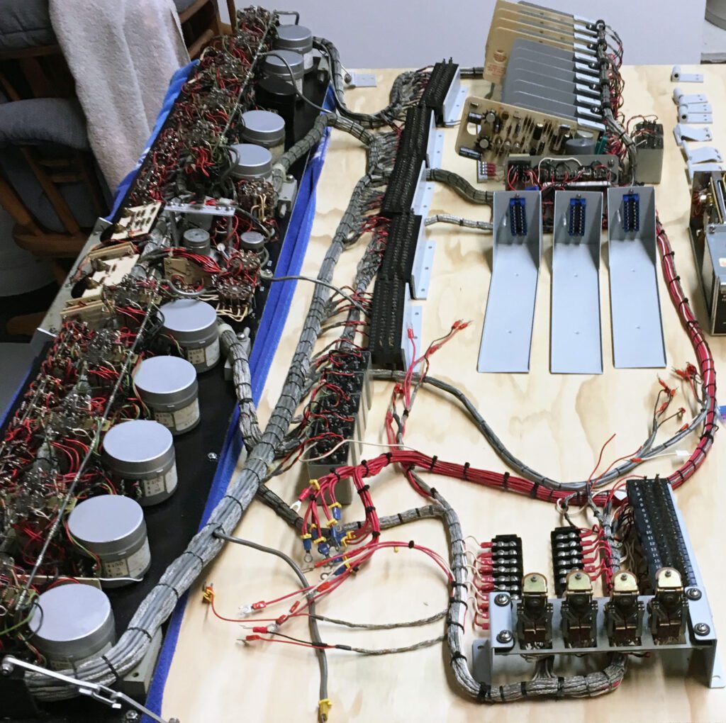
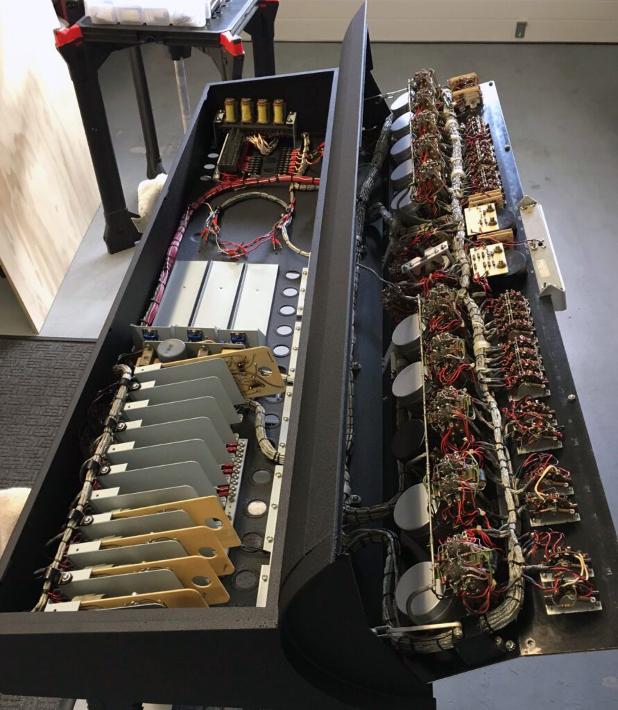
Today was a big day for the console refurbishment project. I created a large work space that allows me to spread out all of the inside hardware and remove the cabinet for refinishing.
With the cabinet completely removed, I will take it to the refinishing shop for a textured power-coat finish. As seen in the previous photos, the original chassis is gray. I plan to change it to black. That way, the entire cabinet will be black. I think that’s a better look, and it is less expensive than doing a two color powdercoat finish.
With the hardware removed from the cabinet, I will be able to do cleanup on the internal components more efficiently. While removing the cabinet is a bit of an extreme step, it will afford a rare opportunity to closely examine all of the internal components and to clean elements that would otherwise be inaccessible. I plan to make the most of this opportunity.
My plan is to focus on the cabinet and associated electronics. I will leave the circuit boards to last, since that’s where most of the time and money will come into play (other than the front panel considerations, as described previously). When I get the cabinet back from the shop, I will begin reassembling the console.
Day 5 – Maximum Disassembly
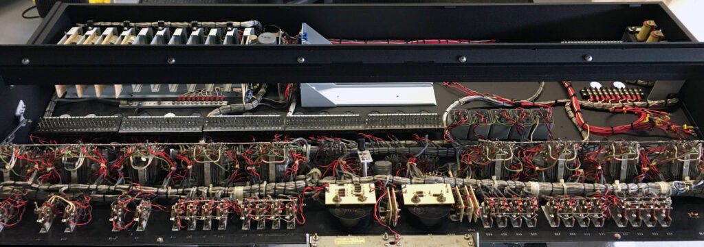
Today marked a turning point for the project: maximum disassembly. At this point, the console is as disassembled as it is going to get. From this point forward, it starts getting put back together.

Having the internal hardware removed from the cabinet provides a good opportunity to examine and work on parts of the console that otherwise are difficult to access. And, even for those parts that are accessible inside the chassis, it is necessary to lean into the unit to perform the work. This is an uncomfortable working arrangement, at best. Also, while working in cramped quarters, it is possible to accidentally damage one component while working on another. There is evidence of such “collateral damage” from previous installations and repairs. This is largely unavoidable in a densely packaged system such as this console.
The last point deserves some additional comment. One important consideration in any refurbishment project is what to fix and what to leave alone. Every engineer knows that judgment calls must be made for this type of work, which are not always clear. For example, while it might be desirable to replace old electrolytic capacitors on a circuit board, the collateral damage to the board itself may outweigh the benefits. Defective components must be replaced, of course, but preventive replacements may damage the board or other components. Judgment calls based on past experience guide us in these cases. For a situation such as I now have, with the console clearly out of service, with no deadline for finishing the project, and with exceptional access to all components, this is the time to make any repairs that might otherwise be considered “optional.” This certainly applies to all hardware in the console. For the circuit boards, however, I plan to be less aggressive about component replacement because of concern about damaging the boards in the process.
It is worth noting that circuit boards manufactured in the 1960s and 70s are far more fragile than modern boards. Differences include the materials used to construct the boards and the traces. The greatest maintenance challenge for old boards is to avoid lifting the component pads. Modern boards have plated-through holes, which are usually quite rugged. Older boards, typically one-sided, can be easily damaged by heat and mechanical stress.
Day 6 – Fixing the Relay Panel
Good progress today on repairing the relay panel that had been damaged sometime in the past. The relay panel is used to mute the monitor speakers when a microphone channel is switched to Program or Audition. There are three sets of monitor speakers—Control Room, Announce Studios, and Lobby. In addition, the relay panel has the ability to activate “on air” warning lights in any of three locations.
You may recall this circuit had some serious problems—two resistors burned in half and four others damaged. All that has been repaired, and the relay panel now looks quite good. When the resistors failed, the heat damaged a couple of wires in the vicinity of the relays. Those wires were also repaired.
Other work today involved cleaning and repairing cabling. Overall, the cabling on the console is in good shape. There are, however, some exceptions—notably the wiring that used to connect the monitor amplifiers. That has now been cleaned up.

Also, I did some work on the microphone preamps and the cue amplifier. As mentioned previously, I plan on eventually re-manufacturing these boards. They are, however, in good enough condition (after some work) to be used, at least initially.
The boards can be re-manufactured at a later date and simply swapped out. That will significantly shorten the time required to get the console working again.
Day 7 – Console Reassembly Begins
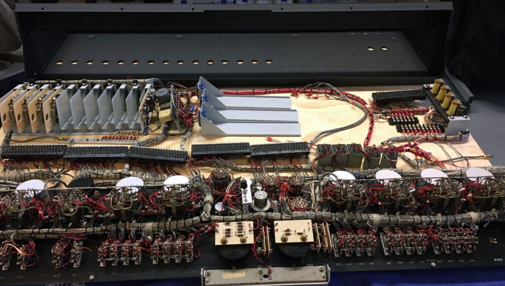
Good progress on reassembling the major components. The card cage was put back together, and connectors attached to the line amplifier modules. The mic preamps can be seen in the photo (the four cards near the bottom). The card at the far end of the card cage is the cue amplifier. The three line amplifiers can be seen, with their covers removed. The covers will be refinished before being installed.
At this point, all wiring has been cleaned up and repaired as needed. All modules and circuit boards, with the exception of the power supply module, have been repaired as needed and cleaned.
Returning to the relay panel repairs detailed above, the reason the resistors failed is a bit of a mystery. The resistors, 47 ohm 2 W, are switched across the monitor amplifier outputs when one of three speaker sets is muted. The resistors are only taking a load when a microphone is on. The rated output of the monitor amplifier is 8 W across 8 ohms. And that assumes a full power sinewave, which is certainly not representative of human speech. And, it is intermittent duty.
The other surprise is that this must have happened over time. The resistors that burned in two certainly announced their failure with the very distinctive smell of over-heated carbon resistors. The four other resistors that were heat-damaged most likely happened over time as well. Perhaps the failure of the load resistors and the fact that the monitor amplifiers are missing are connected. Or, the 2 W resistors were simply under-specified by the manufacturer. When replacement monitor amplifiers are found (or built), this relationship between the amplifiers and the relay panel will be further investigated.
Day 8 – Fixing the Power Supply
Today marked the first serious work on the power supply.
The power supply module provides two outputs for use by various circuits in the console. One is –37 V dc unregulated and the other is –30 V dc regulated. The input to the power supply is a 28 V ac transformer that is mounted external to the console.
Of all the problem areas of the console, the power supply was the greatest concern. It would clearly not operate as found, since two transistors were missing, two zener diodes were missing, and three filter capacitors were either poorly connected on one end, or not connected at all.
There is no easy fix for the power supply. The first step was to completely disassemble the unit. Once that was done, the exact condition of the circuit board and related hardware could be determined.
I do not want to dwell on the poor maintenance this unit received over the years. However, given that the failure of the power supply would take the console out of commission, it is hard to believe that the supply did not receive better care over its operating lifetime.
Moving forward, some parts have been replaced and the missing items have been ordered. Fortunately, the missing components are rather common.
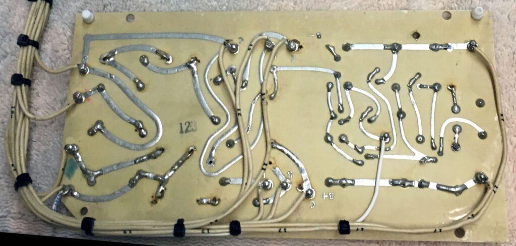
The wiring needed considerable attention, as can be seen in the photo above.
There was also a considerable amount of excess solder on the board, and lots of solder flux. The extra solder was removed with solder braid, and the board thoroughly cleaned with flux remover.
After the cables were organized again (the lacing had come apart over the years), the board began to look like there was hope, as shown in the photo below.
With the components removed, the power supply cabinet will be sandblasted and repainted.
I hope to be able to restore this unit to operating condition. It is possible that building a new power supply will be easier than fixing this one. The supply requirements are modest, and easily achieved today with an integrated circuit regulator. Still, the goal is to return the console to new condition, so I will try and make the original supply work.
I have noted previously on this blog that some transistors are missing from various circuit boards. Curiously, many of the transistors are socket-mounted. So, it is quite possible that they simply fell out during transportation at one point or another. I had forgotten, but many circuit boards in the early days of transistorized designs used sockets for the transistors. The assumption was that the devices might need to be replaced from time to time. As it turned out, the sockets were usually less reliable than the transistors. The practice of using sockets for discreet devices has essentially disappeared; likewise for integrated circuits (except for large processors, memory sticks, gate arrays, and the like).
Day 9 – Cabinet Work Completed
The cabinet work has been completed, and it looks great. The powdercoat finish is perfect. I prefer the all-black finish, rather than the combination black and gray finish of the original.
Reassembly was more of a task than I had expected. Getting the major components out of the cabinet was considerably easier (and faster) than getting them back in. There were two major challenges. First, moving the large sub-assemblies (card cage, relay panel, cue amplifier transformer panel, program amplifier trays, and terminal blocks) back into the cabinet without scratching the finish of either the cabinet or the sub-assemblies. Second, reattaching the front panel to the cabinet.
Reattaching the front panel would be a very difficult (perhaps impossible) step for a single person to accomplish. Fortunately, after Thanksgiving dinner I had two (mostly) willing assistants (daughters) who stepped-in to save the day.
The front panel is held in place by four hinges. Reattaching them was a challenge, given the weight of the front panel and the overall cabinet itself. Once the panel was in place, I (we) attached the bottom trim piece. This was a bit tricky. When installed to precisely line up with the end trim pieces, the front panel would scrape ever so slightly along a portion of the trim. So, a compromise was made to forgo precise lineup with the end piece in exchange for no contact between the front panel and the bottom trim piece.
The scraping situation may have existed for a very long time. The wear pattern of the original paint on the lower trim suggested a problem that had occurred over many years. In any event, no one will notice the slight discontinuity between the end trim piece and the bottom panel trim piece (except for me, of course).
The top cover panel for the cabinet was refinished in the same black satin texture powder-coat as the cabinet itself. I will install the top cover only after all (or nearly all) work has been completed within the chassis. This will afford maximum accessibility to the internal components.
With the benefit of hindsight, the decision to completely remove the cabinet was a good one. I could have just cleaned up the cabinet and repainted it in place (after masking off the font panel). The end result, however, would have been far inferior to the professional finish that I now have. Plus, it would have been very difficult (perhaps impossible) to accomplish the level of work on the internal components documented above without first removing them from the cabinet.
New hardware was used to mount the components in the cabinet. The only exceptions were specialty items that were not commonly available.
Day 10 – Cabinet Reassembly Completed
Cabinet reassembly was completed today. All components have been mounted in the cabinet. It turned out great. Just what I had hoped.
Mounting some of the components proved to be a challenge, but all was accomplished successfully, with a minimum of delay.
The cabinet original finish included some stenciled legends. Those were lost when the cabinet was refinished. I attempted to find suitable stencils to duplicate the original legends. Unfortunately, no practical stencil set could be found that would allow letters and numbers of 1/4-inch in size, which would have matched the style of the originals. The smallest size I could locate (after some searching) was 1/2-inch, which is just too big.
The solution will be to develop a “nameplate” drawing that shows the locations of the major components. The nameplate will also include the manufacturing information (model number, date of manufacture, serial number, etc.). The nameplate will be located on the inside of the cabinet cover. So, when the cover is open, the information will be clearly visible.
And speaking of the cover, it was installed as the last step in the cabinet reassembly process. At some point in the past, an owner had drilled three holes in the cover, presumably to mount a mic boom stand. There aren’t many options to eliminating those holes, other than just putting screws in them, which was the approach I took. With all of the mic mounting options available, it is disappointing that an owner would bring out the drill. It has been theorized that the chipped front end trim piece described above was the result of a mic stand affixed thereto. (Sigh!)
The three gray trays in the middle of the cabinet hold the program line amplifiers. They will be installed after the covers are refinished. At this point, the only components missing are the monitor amplifiers, as detailed previously.
I am now beginning to look closely at the front panel and develop a strategy for restoring it to new condition. I may go with a polycarbonate overlay, rather than attempting to remake the aluminum faceplate. Not sure yet. I have removed the aluminum U-shaped trim piece around the two VU meters. It will be refinished in the same black powder-coat as the cabinet. Also, the meter lamp housing is rather beat-up. It will be refinished as well. Four 28 V bayonet-type lamps are used to illuminate the VU meters. The lamps also serve as a “pilot lamp” to indicate when power is applied to the console.
For the time-being, attention will shift to rebuilding the power supply, and after that, checking the front panel wiring
Day 11 – More Work on the Power Supply
Work continues to rebuild the power supply. This is a major undertaking. The project can be divided into three major stages.
Stage 1 was to repair the circuit board. As noted above, the existing board was in poor condition. Parts were missing and the board had suffered through some sub-optimal service over the years. All of the transistors were mounted in sockets, and unfortunately, some of the sockets had deteriorated. In one case, the transistor would simply fall out. Given this sad state of affairs, I removed all of the sockets from the board and direct-wired the transistors to the board. In addition, there were four zener diodes mounted in transistor sockets. I found this very odd. Here again, the sockets were not reliable and so they were removed. The diodes were soldered directly to the board.
The use of sockets is a bit of a mystery. Some boards in the console use this technique, and in others (such as the mic preamps) the transistors are soldered in place. There are two obvious explanations. First, the reliability of the devices was uncertain and so using socketed devices would allow for easy repair in a timely manner. Second, there was concern about device failure due to excessive heat during board construction and/or maintenance.
For modern circuit boards, most work is done using soldering irons rated for 25 W or less. Back in the day, however, soldering irons were big and hot. And then there were soldering guns. So, there may be some validity to the second theory. In any event, the sockets are gone and the board looks better for it.
Stage 2 will be to refinish the cabinet. The old cabinet was scratched and otherwise beat up. I’m not sure how it could have become so physically stressed while in the protection of the cabinet. Anyway, a trip to the refinishing shop will get all of the old paint off and a new coat of paint applied.
Stage 3 will be reassembly. Testing will come later, after initial work on the front panel has been completed.
While the power supply assembly is coming together nicely, I may still replace it with a modern IC-based design. This is easily accomplished. Before going there, however, I want to get the original power supply back into operating condition, if possible.
Day 12 – The Front Panel
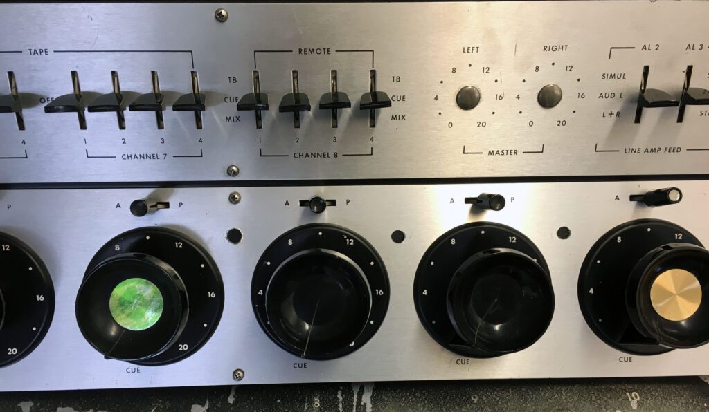
The focus of today’s work was the front panel. All of the wiring was inspected and cleaned-up as needed. In addition, all of the attenuators were opened and cleaned. The front panel knobs and attenuator trim plates for the 10 mixer channels were also removed in preparation for some serious work on the front panel.
It is evident from the condition of several of the attenuators that they had been serviced or replaced at some point in the past. In a few cases the wiring job left something to be desired. Those shortcoming have now been addressed and the wiring has been put back the way it should be.
Fortunately, the attenuators can be easily removed from the front panel (as shown in the photo), and they can then be cleaned without messing up the surrounding circuitry with over-spray from contact cleaner. All of the attenuators are in good mechanical condition. There are no obvious signs of damage. Contacts that are visible through removal of the back cover look good.
I have noted previously that some modifications have been made to certain parts of the console. That extended to the front panel as well. Fortunately, the changes were confined to the microphone input switches. Pads are used to adjust Mono/Stereo switching levels. Two of the three pads had been changed. The close-up photo on the right shows one of the troublesome switches.
Fortunately, the switches are accessible and the correct resistors easily obtained. Work was slow and detailed, but now it’s done.
All of the off-standard changes made to the console have been removed and the console is now in the as-designed state.
The need to customize a console such as this is understandable. However, considerable flexibility is designed into the unit, with most critical circuits (including the microphone inputs/outputs) available on one or more terminal strips inside the chassis. The modifications should have been made there, not on the front panel.
There are many drawbacks to these sorts of custom changes. First is that the changes are not documented. Or, if they were, the documentation has long since been lost. Second, attempting to improve on a design that has been used in a large number of installations over a long period of time seems dubious.
Enough complaining. I knew work would be required to get the console to the condition we wanted. And, now that those problems are fixed, we are done with them.
Day 13 – Program Amplifiers Installed
Another trip to the powdercoat shop brought back the cases for the Program/Audition line amplifiers. They were assembled and installed.

Also back from the shop was the right side cabinet trim piece. This, you will recall, is the piece with the chipped end. The cabinet looks very nice, and the trim piece (even though it has a flaw) will suffice for now. The only practical solution to fixing the chip may be to replace the piece. This will require finding another Gates console of this series. Candidates include those shown in the Gates advertisement at the top of this blog. The search continues, but at a low priority.
The last trim piece to be refinished was the one over the meter bridge, as shown in the photo below. In the original design, this piece was anodized aluminum. That looked fine, but the finish really didn’t match well with the aluminum front panels (upper and lower), which are anodized brushed aluminum. So, I had the meter trim piece refinished in the same satin black texture powder-coat as the rest of the cabinet. I like the look.
The console, as built, uses 7 matching transformers (Triad A-21) for various functions. There is a position for an 8th device. I was able to find an A-21 on eBay for a reasonable price. After cleaning it up, I installed it in the cabinet. I have no particular need for the transformer right now, but it may come in handy later.
Other work today included mounting replacement Master Gain potentiometers on the front panel. When I purchased the console, both of the gain pots were missing. That is fixed now. I am also looking for suitable replacement knobs for the Master Gain controls. There are a couple of possibilities, which I am pursuing.
As the cabinet continues to look better, I am more convinced than ever that I will want to have the front panel aluminum pieces remade. In the case of the top panel, I can probably use the existing aluminum and have it refinished with new legends applied. (A thorough cleaning may also suffice.) For the lower piece, I will need to have the panel reproduced. With the three unneeded holes (as discussed previously), there is really no good option for fixing this, other than starting over.
I have removed the ten attenuator trim pieces from the front panel. They will be refinished and new legends applied.
Day 14 – Power Supply Work Completed
The power supply rebuild project was finished today. As outlined above, there was a lot of work necessary to get the power supply back into operating condition. Aside from the cleanup and component replacements detailed previously, the cabinet was refinished and the circuit board thoroughly cleaned.
Upon completion of this work, the unit was powered-up for for testing. The unregulated –37 Vdc supply worked, but the –30 Vdc regulated supply did not. The trouble was traced to a faulty transistor, which fortunately was relatively common and a replacement easily found.
It was evident that some work had been done on the unit before I purchased it. The faulty transistor may have been the cause of those earlier problems.

With the new transistor in the circuit, the power supply started up perfectly. When unloaded, there is a wide operating range available through adjustment of R12, from a low of –20 V to a high of –36 V. The supply was set for –30 V dc and run for several hours. There was no noticeable drift and no excessive heating of components.
Still to come is a nameplate for the power supply giving the operating ratings and connection pin-out. This will be installed later, after the piece is produced by Metalphoto of Cincinnati, which I use for all polycarbonate overlays.
In the coming days, the power supply will be installed in the console and the various circuit boards powered up. I plan on doing this one board/module at a time in order to check the operation of each circuit. Keep in mind that the console has not seen powered operation for many years, so a go-slow approach is advisable.
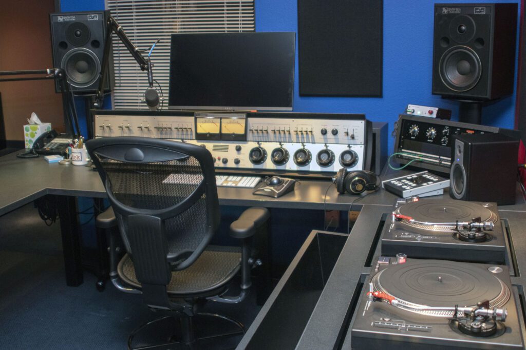
With installation of the power supply, the Executive console is ready for tests. Further work is planned, notably on the front panel. For the moment, however, the project has reached completion of Phase 1.
Phase 2 of the Executive Audio Console restoration project is documented in the blog Gates Executive Audio Console Restoration, Part 2.